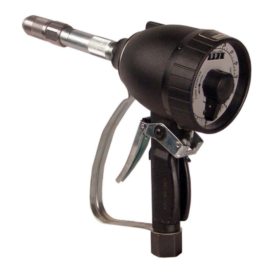
Alemite 3693-C Instrukcja serwisowa - Strona 7
Przeglądaj online lub pobierz pdf Instrukcja serwisowa dla Jednostka sterująca Alemite 3693-C. Alemite 3693-C 12 stron. Preset metered control valve
Również dla Alemite 3693-C: Instrukcja serwisowa (8 strony)

Pointer, cam and dial
assembly
23 Install dial (27) onto cam (17).
24 Install rollers (19) into cam.
NOTE
Make sure spring (18) is against
right-angled end of notch in cam (17).
25 Install springs (18) into cam (17).
26 Install and seat pointer (24) onto
cam (17).
NOTE
Make sure three holes on dial engage
with register posts.
27 Install and seat pointer (24), cam (17),
and dial assembly (27) onto shaft of
spindle and gear assembly (7).
NOTE
Make sure lock pawl (14) fits properly
into hole of dial (27).
Pointer setscrew must point toward
flat on spindle and gear assembly (7).
28 Tighten pointer setscrew onto shaft of
spindle and gear assembly (7).
29 Turn pointer (24) counter-clockwise and
set to zero.
30 Install shroud (25) with notch downward
onto housing (8).
31 Install screws (26) that secure shroud to
housing (8).
32 Tighten each screw securely.
Lever assembly
33 Install quad rings (36) onto each end of
cam (37).
34 Install cam (37) into housing (8).
NOTE
Use care passing quad rings (36).
*
Indicates change.
35 Install lever assembly (40) onto cam (37).
NOTE
Reposition cam (37) as required to
ensure lever assembly properly meshes.
36 Install lock bar and screw assembly (39)
onto cam (37) with screw in lock bar so
that screw assembly meshes properly
with lock pawl.
37 Install screws (38) that secure lever
assembly and lock bar and screw
assembly to cam.
38 Tighten screws securely.
Valve and inlet swivel
assembly
39 Install valve sleeve (29) with unslotted
end into housing (8).
40 Install valve assembly (28) stem first into
small end of spring (30).
41 Install valve assembly and spring
horizontally into housing (8) so that valve
assembly does not shift.
42 Install screen (31) into spring.
43 Install o-ring (33) onto adapter (34).
44 Screw adapter into housing (8) and
tighten to ft. lbs. (26 Nm).
45 Screw swivel assembly (35) with thread
sealant into adapter.
46 Tighten swivel assembly securely.
Extension
NOTE*
Do not apply thread sealant to first two
threads. Contamination can occur.
Apply thread sealant to all other pipe
thread connections prior to assembly.
48 Screw extension (2) into cap (3).
49 Tighten extension securely.
50 Screw nozzle assembly (1) onto
extension.
51 Tighten nozzle assembly securely.
