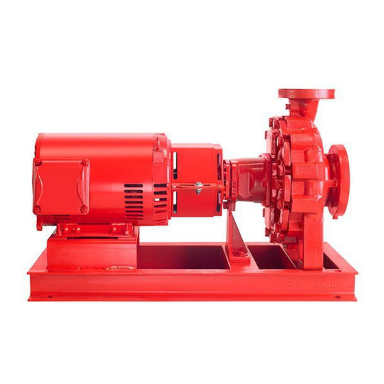
Armstrong 4030 Instrukcja instalacji i obsługi - Strona 5
Przeglądaj online lub pobierz pdf Instrukcja instalacji i obsługi dla Pompa wodna Armstrong 4030. Armstrong 4030 12 stron. Base mounted pump
Również dla Armstrong 4030: Instrukcja instalacji i obsługi (12 strony)

limitations
See pump nameplate for speed, duty and maximum
pressure/temperature limitations. These limits must
not, under any circumstances be exceeded without prior
consultation with Armstrong.
important:
Do not run the pump for any length of time under very
low flow conditions or with the discharge valve closed
To do so could cause the water in the casing to reach
super heated steam conditions and will cause
premature failure and could cause serious and dramatic
damage to the pump and surrounding area.
installation
1.
location
• In open systems, locate the unit as close as practical to
the liquid being pumped, with a short, direct suction pipe.
Ensure adequate space is left above and around the unit
for operation, maintenance, service and inspection of
parts
• In closed systems, where possible, the pumps should be
installed immediately downstream of the expansion tank/
make-up connection. This is the point of zero pressure
change and is necessary for effective pump operation. Do
not install more than one expansion tank connection into
any closed hydronic system
• Electric motor driven pumps should not be located in
damp or dusty location without special protection
• Airflow into the motor and/or motor fan should not be
obstructed
2.
installation
• Recommended installation arrangements are:
2 .1
foundation
The foundation should be sufficiently substantial to absorb
any vibration and to form a permanent rigid support for the
baseplate. This is essential in maintaining the alignment of
a direct connected unit. A good foundation should weigh
approx. 2.5 times the shipping weight of the pump. In
building the foundation, make ample allowance for grouting.
Foundation bolts of the proper size should be arranged as
shown, with a pipe sleeve embedded in the concrete to
permit adjustment of the bolts after the concrete has been
poured. Use sleeves with a diameter 2.5 times the diameter
of the bolts.
Series 4030
Base mounted pump
Locate the pump on its foundation holes
using the motor feet as a template.
Drill four holes of the required size and
insert the anchors.
Take the tamping tool (supplied with the
anchors) and drive home the lead sleeve
until it is below the level of the foundation and firmly fixed in
the concrete.
2 . 2 levelling
When the unit has been placed on it's
foundation, slacken off the coupling
setscrews and slide back the coupling
halves so that the pump and motor
shafts are free to rotate independently.
Re-tighten the setscrews in this
position. Do not re-connect the coupling until after the unit
has been piped up, finally aligned and checked for correct
direction of rotation.
Insert metal wedges approx. 15mm thick on either side of
the foundation bolts under the baseplate as shown. Adjust
wedges until the shafts of the pump and motor are level.
On flanged pumps check suction and discharge flanges for
vertical or horizontal position using a level and correct as
necessary by adjusting the wedges. When the baseplate is
completely level, the foundation bolts should be tightened
evenly and firmly. Do not over-tighten bolts at this stage.
2 .3 alignment
The pump unit is accurately aligned in our factory prior to
being shipped. However all baseplates are flexible to some
extent and must not be relied upon to maintain factory
alignment. Re-alignment is necessary as follows:
a
After the unit has been set level on its foundation
b
After the grout has set and the foundation bolts have
been tightened
c
After the pipes have been connected
Accurate alignment is absolutely essential, proper mechani-
cal operation of the equipment cannot be guaranteed unless
the factory alignment is reproduced in the field.
Coupling Alignment
Check the alignment by placing a
straight edge across the coupling rims
at the top, bottom and both sides. Care
must be taken to have the straight edge
parallel to the axis of the pump and motor shaft. Alignment is
obtained when the straight edge rests evenly on both rims in
all four positions.
Adjust as necessary by placing shims under the motor feet.
in sta l l a t io n &
o pera t ing instr uct io n s
5
