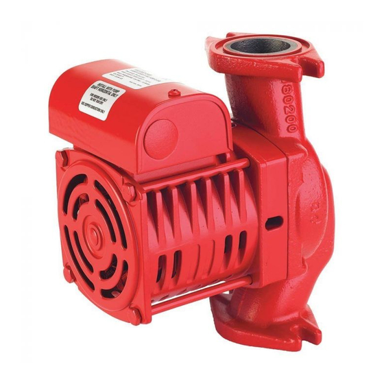
Armstrong ARMflo E8.2 E2 Series Instrukcja instalacji i obsługi
Przeglądaj online lub pobierz pdf Instrukcja instalacji i obsługi dla System wodny Armstrong ARMflo E8.2 E2 Series. Armstrong ARMflo E8.2 E2 Series 4 stron. High efficiency circulator

READ CAREFULLY BEFORE INSTALLING & OPERATING THE CIRCULATOR
INSTALLER
You are about to install an ARMflo E Series circulator - a high-efficiency pump from Armstrong. ARMflo E Series
circulators are designed for heating and cooling in hydronic, geothermal or solar systems, circulating water or
ethylene or propylene glycol/water solutions. For pumping domestic (potable) water, Armstrong recommends the use
of circulators with bronze body construction.
The ARMflo E Series circulators are extremely efficient and quiet and utilize a state of the art permanently lubricated
bearing system designed for many years of trouble-free operation. They feature a permanent-split capacitor motor
with thermal protection.
OPERATING LIMITS
Maximum operating pressure:
Maximum operating temperature: All Standard Models
Electrical Rating: For models with 1/6 hp motors: 120 V, 1 Phase, 60 Hz or 208 / 240 V, 1 Phase, 60 Hz
When unpacking the circulator, inspect for any damage that may have occurred during transit. Check for loose,
missing or damaged parts.
Before installing the circulator, proper installation practice recommends a thorough flush of the hydronic system,
ensuring removal of all foreign materials.
C
L
ARMflo E Series
High Efficiency Circulator
: PLEASE LEAVE THIS MANUAL FOR THE OWNER'S USE
150 psi (1034 kPa)
Models Ending in -TE – 150°F (65°C)
For models with 2/5 hp motors: 120 V, 1 Phase, 60 Hz or 208 / 240 / 277 V, 1 Phase, 60 Hz
THIS PUMP IS FOR INDOOR USE ONLY
Motor Shaft
(internal)
INSTALLATION AND OPERATING INSTRUCTIONS
– 230°F (110°C)
Warning! "Mount with motor shaft horizontal and terminal
box above centerline (C
L
The circulator is supplied for "up" discharge.
For alternate discharge orientation:
1. Loosen the 4 motor mounting bolts.
2. Rotate the volute to match piping orientation.
3. Observe flow direction arrow on volute.
4. Ensure volute gasket is properly seated.
5. Retighten mounting bolts evenly to 5lb-ft (6.7N-m).
6. Ensure the impeller spins freely.
Page 1 of 4
FILE NO.:
DATE:
SUPERSEDES: 10.84
DATE:
) only!"
10.84
Jul. 20, 2010
Feb. 23, 2006
