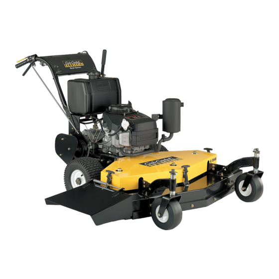
Cub Cadet Commercial G 1332 Instrukcja obsługi i serwisowania - Strona 6
Przeglądaj online lub pobierz pdf Instrukcja obsługi i serwisowania dla Kosiarka Cub Cadet Commercial G 1332. Cub Cadet Commercial G 1332 16 stron. Walk-behind commercial rotary mowers

SPECIFICATIONS
Engine:
Type:
Air Cleaner:
Lube System:
Fuel Tank:
Transmission:
Traction Drive:
Ground Speed:
Drive Wheels:
Brakes:
Controls:
Frame
Handles
OPERATING INSTRUCTIONS
A. Controls
1. Ignition Switch:
(Recoil Start)
Located in the center of the control panel between the
handles. When the key is inserted and turned clockwise
90 degrees, the engine can be started if the
transmission shift lever is in neutral and the blade clutch
is disengaged.
(Electric Start)
Located in the center of the control panel between the
handles. When the key is inserted and turned clockwise
90 degrees, the engine will start if the transmission shift
lever is in neutral and the blade clutch is disengaged.
2. Fuel Shutoff Valve:
Located under the fuel tank in the opening of the handle
mount frame. The handle turns 90 degrees. When the
handle is in a horizontal position, it will shut off the flow
of fuel to the engine. When it is turned to a vertical
position, it will open and allow fuel to flow to the engine.
Anytime the mower is being trailered or, if the mower will
not be in use for 30 minutes or more, close the fuel
shutoff valve to prevent flooding the engine.
3. Engine Throttle:
Located on the right side of the control panel between
the handles. Moving the throttle lever from the front to
the rear will increase the engine speed from slow to fast.
To start the engine, set the throttle all the way to the
rear in the "Choke" position. After the engine starts,
move the throttle halfway between slow and fast.
4. Recoil Starter:
Located on the top of the engine. To start the engine,
13 or 15 HP Kawasaki.
4-cycle, single-cylinder, recoil start.
Dual element, dry-type.
Pressurized.
5 gallons, polyethylene.
5 speeds forward and 1 speed reverse.
Double V-belts.
2 to 4.5 MPH maximum.
13 x 6.50-6 pneumatic tires mounted on steel wheels with ball bearings.
Two 6-inch drum, external band type.
Right and left steering/brake levers; over-center blade clutch; transmission shift
lever; engine throttle; cutter blade,transmission neutral and operator presence safety
group; key-type ignition switch.
Steel Plate. All welded construction.
1-1/4" diameter, tubular steel, adjustable.
Cutting Width:
32"
Overall Width:
33"
Number of Blades:
2
Height of Cut:
2 to 4 inches in 1/4" increments.
Deck Material:
10 gauge steel top with 7 gauge steel skirt.
Casters
9 x 3.50-4, 4-ply tires with inner tubes.
Wheels have open-cage roller bearings.
POWER UNIT
CUTTING DECK
36"
48"
37"
49"
2
3
set the throttle on "Choke" and grasp the starter grip and
pull slowly until the starter engages. Then pull the cord
rapidly to overcome compression, prevent kickback and
start the engine. Repeat if necessary with the throttle
pushed halfway back to the "Slow" position.
9
7
Figure 1 The Control Panel
1. Ignition Switch
6. Blade Clutch Lever or
Electric Blade Clutch
8. Neutral Latch Levers
5. Transmission Shift Lever:
Located under the control panel. The lever has seven
positions moving from the left to the right:
Reverse Gear, Neutral, First Gear, Second Gear, Third
Gear, Fourth Gear and Fifth Gear. The lever must be in
the Neutral position in order to start the engine. Never
attempt to mow in Fifth Gear. Fifth Gear should be used
for transport only. Note: DO NOT shift the transmission
from one forward gear to another while moving.
6
52"
53"
3
8
1
3
3. Engine Throttle
7. Right Steering Brake Lever
(not shown)
9. Operator Presence Lever
6
