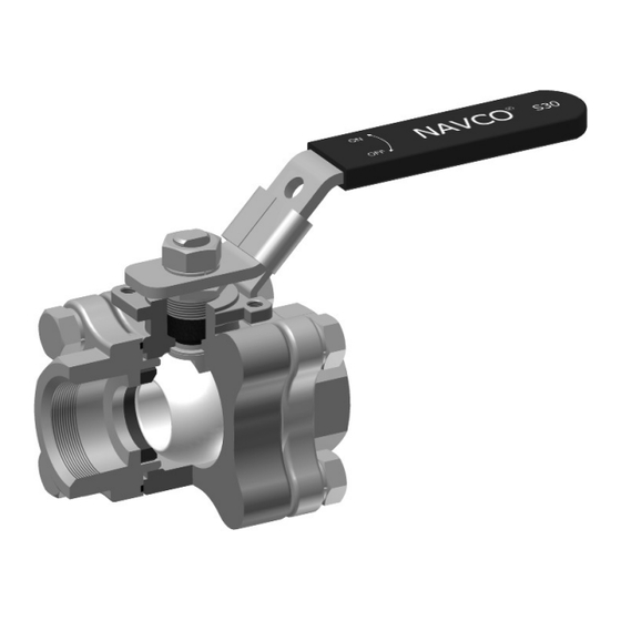
Cameron NAVCO S30 Instrukcja instalacji, obsługi i konserwacji - Strona 8
Przeglądaj online lub pobierz pdf Instrukcja instalacji, obsługi i konserwacji dla Jednostka sterująca Cameron NAVCO S30. Cameron NAVCO S30 10 stron. Three piece swing out ball valve

Reassembly
Cameron recommends replacement of all soft parts whenever the valve is disassembled for reconditioning.
• Lightly grease the thrust washer (05), the stem seal area, and the threads of the stem. Insert thrust washer
(05) into the body shoulder.
• Insert stem (11) up through the body cavity, through the thrust washer (05) and body stem bore. Make sure
the stem shoulder is firmly against the thrust washer (05) to where the stem is extended out of the top of the
body as far as possible.
• Press the body seals (16) into the grooves of each cap (03).
• Turn the stem (11) to a position with the ball/stem tang flats parallel to the cavity.
• Before installing the ball, make a visual inspection for any nicks, scratches, pitting or corrosion. Install the
ball (02) into the body (01), lining up the ball slot with the stem drive tang. The ball should be in the
closed position.
• Rotate ball (02) to the open position.
• Install joint gaskets (06) for each side of the body (01).
• Apply grease to the face of each seat (06) and simultaneously press seats into i.d. of the body bore and joint
gaskets (06) until contact is made with the ball.
• Carefully, avoiding damage to the seats and seals during assembly, swing valve body section back into posi-
tion while holding the seats and gaskets in place.
• Install and hand tighten all body bolts (09) and washers (08).
• Carefully install packing (7) over stem and press down into the counter bore of the body top pad.
• Install packing gland nut (10) over stem and thread into body until hand tight. Adjust the torque of the
packing gland to the following values:
½"
¾" and 1"
1-1/4"
1-1/2" and 2"
• Evenly tighten bolts (09) in an alternating sequence, until body (01) and cap (03) mating surfaces are metal to
metal. Do not exceed the torque values listed below.
½" and ¾"
1" and 1-1/4"
1-1/2"
2"
Installation, Operation and Maintenance Manual
10 ft-lbs
15 ft-lbs
22 ft-lbs
26 ft-lbs
5 ft-lbs
10 ft-lbs
27 ft-lbs
42 ft-lbs
8
D I S T R I B U T E D V A L V E S
03/2011 / IOM-NAV-BALL-S30
