Camille Bauer SINEAX G 537 Instrukcja obsługi - Strona 9
Przeglądaj online lub pobierz pdf Instrukcja obsługi dla Przetwornik Camille Bauer SINEAX G 537. Camille Bauer SINEAX G 537 12 stron. Transducer for phase angle difference

Operating Instructions
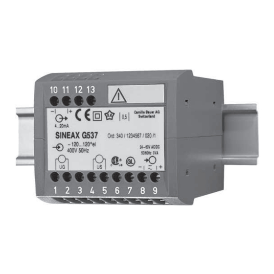
Transducer for phase angle difference SINEAX G 537
Safety precautions to be strictly observed are marked
with following symbols in the Operating Instructions:
Contents
1. Read fi rst and then ... ................................................ 9
2. Brief description .......................................................... 9
3. Technical data ............................................................. 9
4. Mounting ................................................................... 10
5. Electrical connections ............................................... 10
6. Commissioning and maintenance ............................. 11
7. Releasing the transducer .......................................... 11
8. Dimensional drawing ................................................. 11
9. Instruments admissions ............................................ 11
10. Declaration of conformity .......................................... 12
1. Read fi rst and then ...
The proper and safe operation of the device
assumes that the Operating Instructions is
read carefully and the safety warnings given
in the various Sections
4. Mounting
5. Electrical connections
are observed.
The device should only be handled by appropriately
trained personnel who are familiar with it and authorised
to work in electrical installations.
Unauthorized repair or alteration of the unit invalidates
the warranty.
2. Brief description
The transducer SINEAX G 537 converts the phase angle diffe-
rence of two synchronised supplies into a load independent
DC current or a load independent DC voltage proportional
to the measured value.
3. Technical data
Measuring input
Measuring range:
Within - 180 - 0 - + 180 °el,
but clear indication only to
-175-0- +175 °el;
measuring span ≥ 20 °el
Nominal frequency:
10 to 1500 Hz (min. 40 Hz, max. 400
Hz with power supply from measu-
ring input)
Nominal input
voltages:
Generator and bus bar
≥ 10 - 230 V or 230 - 690 V
(min. 24 V, max. 230 V, acc. to build-in
power pack, with power supply from
measuring input)
Measuring output
DC current:
0 - 1 to 0 - 20 mA
0.2 - 1 to 4 - 20 mA
± 1 to ± 20 mA
Burden voltage:
- 12 / 15 V
External resistance:
R
ext
resp. ≤
I
AN
DC voltage:
0 - 1 to 0 - 10 V
0.2 - 1 to 2 - 10 V
± 1 to ± 10 V
Load capacity:
Max. 4 mA
Power supply
AC/DC power pack (DC or 50/60 Hz)
Rated voltage
85 - 230 V DC / AC
24 - 60 V DC / AC
Power consumption:
3 VA
Options
Connected to the low
tension terminal side:
24 V AC or 24-60 V DC, see Fig. 4
Power supply from
measuring input
(self powered):
24 - 60 V AC or 85 - 230 V AC,
see Fig. 3
Please note the max. and min. meas. input voltage!
Type label
Input voltage
inscription
range
= internal power
supply range
Self powered
by 1/2
24 - 60 V AC
(int. 24-60 V)
Self powered
by 1/2
85 - 230 V AC
(int. 85-230 V)
15 V
max. [kΩ] ≤
I
[mA]
AN
- 12 V
- I
[mA]
AN
= Full output value
Tolerance
DC - 15 to + 33%
AC ± 15%
Tolerance Power
supply
connec-
tion
Internal
± 15%
mea-
suring
input
9
