esera automation 11228 V2 Podręcznik użytkownika - Strona 5
Przeglądaj online lub pobierz pdf Podręcznik użytkownika dla Systemy wejścia/wyjścia esera automation 11228 V2. esera automation 11228 V2 7 stron. 8-fold high power switching module / binary output w/auto-e-connect

Art. No. 11228 V2
9
8-fold digital input, pushbutton interface
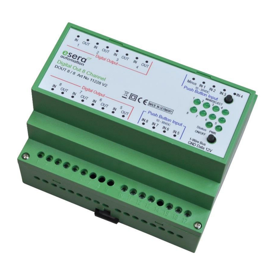
In addition to manual operation (top of module) and the 1-Wire interface, the module also features a 8-fold push-
button interface (8 x digital input) for switching the outputs.
A short input signal (keystroke, 10-30VDC inputs) is sufficient to switch an output to the corresponding input.
The 8-fold push-button interface is intended for switching lights or sockets in living areas, e.g. by means of light
switches or motion detectors with pulse output. This ensures very fast switching even without system control.
The pulse control, comparable to an automatic staircase lighting controller, allows any number of light scanners
and motion detectors to be connected in parallel.
For further details on the ESERA-Automation lighting system please refer to our website:
https://www.esera.de/smart-home/anwendungsbeispiele/lichtsteuerung/
In addition to light scanners, any other pulse control signal can be used to switch the outputs.
All three interfaces, manual mode, 1-Wire and push-button interface, operate in parallel on the outputs. An output
switched e.g. by the 1-Wire interface can be switched off or on manually or via the push-button interface.
Light scanners for light on/off control can be connected to the push-button interface. Normal photoelectric
proximity switches from all switch manufacturers can be used for this purpose.
Inside the module, a µcontroller is responsible for querying the pushbuttons, the 1-wire interface and controlling
the relays. The push-button interface is interrogated via edge interrogation.
10
Software / Control
The 1-Wire interface of the 8-fold digital output 8/8 is controlled by standard commands for the device DS2408.
The pushbutton interface and the relay status are output via the DS2408 variables. Outputs switched via the
push-button interface or manual mode can be read back via the 1-wire interface.
11
Control per 1-Wire Controller / 1-Wire Gateway
The 1-Wire interface of the 8-fold digital output 8/8 is controlled by standard commands for the device DS2408.
The outputs switched via the push-button interface or manual mode can be read back via the 1-wire interface.
The 8-fold High Power switching module can easily be controlled via a 1-Wire Controller / 1-Wire Gateway. Two
commands are available for this purpose. Below are the two commands.
11.1
Switching of one output relay
To switch a relay output, use the following command to set only the selected output to 0 or 1.
Command: SET,OWD,OUT,OWD-number, output, value
Example: set,owd,out,2,1,1 => OWD number 2, output 2 is switched to "On". After switching the output, the new
status is output as confirmation.
11.2
Switching of all output relays (PORT)
There are applications where it is necessary to switch all outputs with one command.
With one command, all outputs of the 1-Wire module are set to a certain state, which means that the previous
relay status is overwritten.
The 1-Wire Controller / 1-Wire Gateway takes over the adaptation of commands to the connected 1-Wire 8-fold
digital output 8/8.
The output value is output as decimal value 0-254. Each relay output has a value that is summed.
Output 1 = 1, Output 2 = 2, Output 3 = 4, Output 4 = 8, Output 5 = 16, Output 6 = 32,
Output 7 = 64, output 8 = 128.
If, for example, you want to switch outputs 1, 3 and 5 to 1, add the output values together.
Here e.g. 1 + 4 + 16 = 21
All other relay outputs are switched to 0. If all outputs are to be set to 0 or switched off, the output value is 0.
Permissible output values for 1-Wire digital outputs: 0 – 255
All rights reserved. Reproduction as well as electronic duplication of this user guide, complete or in part, requires the written consent of
ESERA GmbH. Errors and technical modification subject to change. ESERA GmbH, ESERA-Automation 2020
www.esera.de
11228 V2.0 R1.0 Manual
Page 5 of 7
