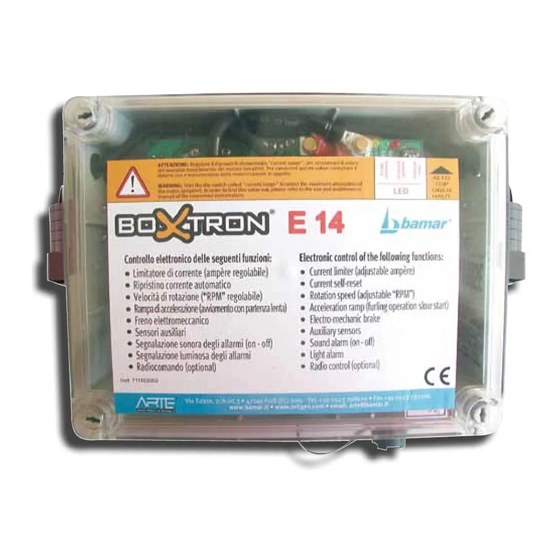
bamar BOXTRON E14 Instrukcja obsługi - Strona 12
Przeglądaj online lub pobierz pdf Instrukcja obsługi dla Kontroler bamar BOXTRON E14. bamar BOXTRON E14 20 stron. Electric control box for electric motorizations

PERICOLO DI FOLGORAZIONE
C-8
TABELLA PER LA SELEZIONE DELLE
ATTENZIONE
SOGLIE DI INTERVENTO DI MASSIMA
CORRENTE "CURRENT RANGE" AMPÈRE (A)
AVVERTENZA
Tabella valida per BOXTRON
®
dal N° 0000E e successivi.
RISPETTA L'AMBIENTE
10 A
15 A
RGEEL 80/24V
RGIEL 80/24V
RRGEEL 80/24V
RRGIEL 80/24V
20 A
RGEEL 80/12V
RGIEL 80/12V
RRGEEL 80/12V
RRGIEL 80/12V
BWSE 5t 24V
30 A
BFBME 110 24V
BFBME 110 48V
BFBME 140 24V
RGEEL 110/24V
RGIEL 110/24V
RRGEEL 110/24V
RRGIEL 110/24V
C-9
SIGNIFICATO SEGNALAZIONE LED
•
LED GIALLO (Y):
Il LED giallo spento indica che il fusibile conduce. Il LED giallo acceso
indica che il fusibile F1 è interrotto e quindi manca alimentazione al
BOXTRON
E14.
®
Se il LED giallo è acceso il fusibile F1 deve essere sostituito con altro
fusibile di corretto amperaggio.
L'interruzione di questo fusibile non spegne il LED verde (G).
•
LED VERDE (G):
Il LED verde acceso indica la corretta alimentazione elettrica del
BOXTRON
E14.
®
Il LED verde spento indica la mancata alimentazione elettrica al
BOXTRON
E14.
®
•
LED ROSSO (R):
Il LED rosso spento indica che non sono segnalati errori oppure il
BOXTRON
E14 è spento.
®
Il LED rosso acceso a luce fissa, indica che il BOXTRON
lavorando regolarmente (motore in azione).
Il LED rosso che lampeggia rapidamente indica uno stato di anomalia
o errore.
12
E14 con numero seriale di identificazione
40 A
BWSE 5t 12V
50 A
BFBME 110 12V
BFBME 140 12V
EJF 1 24V
MEJ 1 24V
RGEL 65 24V
TBEL 65 24V
RLG-CODE SE WL5T
CODE PE 8-10T
60 A
RGIEL 110/12V
RRGIEL 110/12V
70 A
BWSE 8-10T 24V
ISTRUZIONI DI MONTAGGIO E USO
DANGER OF ELECTROCUTION
INSTALLATION AND USE
C-8
DIAGRAM FOR THE SELECTION OF THE
CAUTION
MAXIMUM CURRENT INTERVENTION
THRESHOLD-AMPÈRE (A) "CURRENT RANGE"
WARNING
Diagram suitable for BOXTRON
0000E and above.
RESPECT THE ENVIRONMENT
C-9
DESCRIPTION OF LED SIGNALS
•
YELLOW LED (Y):
If the yellow LED is off, it shows the fuse conducts. If it is on, it shows
the F1 fuse is interrupted, therefore the BOXTRON
If the yellow LED is on, the F1 fuse should be replaced with another
one having the right amperage.
The interruption of this fuse does not turn off the green LED (G).
•
GREEN LED (G):
If the green LED is on, it shows a correct electric supply to the
BOXTRON
®
If the green LED is off, it shows a lack of electric supply to the
BOXTRON
®
•
RED LED (R):
If the red LED is off, it either shows no errors occurred, or the
BOXTRON
®
E14 sta
®
If the red LED is on, with fixed light, it shows the BOXTRON
working (motor in action).
If the red LED is rapidly flashing is shows that an error or anomaly
occurred.
E14 with identification number from
®
A
80 A
GFSE 12 24V
90 A
100 A
EJF 1 12V
EJF 2 24V
MEJ 1 12V
RGEL 65 12V
TBEL 65 12V
GFSE 8 24V
110 A
BFBME 182 24V
E14.
E14.
E14 is turned off.
um_boxtron e14_it-en_rev. 1.0
C
120 A
RGEEL 130 24V
RRGEEL 130 24V
RGEL 95 24V
TBEL 95 24V
GFSE 8 12V
130 A
GFSE 16 24V
140 A
MEJ 2 24V
RGEEL 160 24V
RRGEEL 160 24V
MEJ 3 24V
EJF 3 24V
150 A
E14 is powerless.
®
E14 is
®
