EDI DA-300 Instrukcja obsługi - Strona 6
Przeglądaj online lub pobierz pdf Instrukcja obsługi dla Sprzęt testowy EDI DA-300. EDI DA-300 7 stron. Io tester

SETUP:
1.
Verify the harnesses are connected securely to the DA-300
®
300
IO tester. The harnesses are keyed to go into only their respective ports on both
the IO tester and DA-300
2.
Verify all top panel labeled switches are off.
3.
Turn IO Tester on by front panel ON/OFF toggle switch.
A.
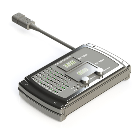
Apply an AC or DC voltage to a single DC or AC Analog input of DA unit
under test.
1.
Select and flip the toggle switch labeled for the required Analog Input of the
DA-300
2.
If a DC Analog channel is to be tested, adjust the DC voltage displayed by
top meter to the required start value by rotating the front panel left knob.
Increase voltage by rotating knob clockwise; and decrease DC voltage by
rotating it counter clockwise.
3.
If an AC Analog channel is to be tested, adjust the AC voltage displayed by
bottom larger meter to the required start value by rotating the front panel
right knob. Increase voltage by rotating knob counter clockwise; and
decrease DC voltage by rotating it clockwise.
4.
Freely adjust the DC or AC voltages as required by the test for this DA-300
input channel.
5.
When the test for this channel is complete, flip the toggle switch of step 1
back down.
B.
Apply simultaneous AC or DC voltages to multiple DC or AC Analog inputs
of DA-300
1.
Select and flip the toggle switches labeled for the required Analog Inputs of
the DA-300
2.
If DC Analog channels are to be tested, adjust the DC voltage displayed by
top meter to the required start value by rotating the front panel left knob.
Increase voltage by rotating knob clockwise; and decrease DC voltage by
rotating it counter clockwise. (All DC channels selected in step 1 will receive
the same adjusted DC voltage.)
3.
If AC Analog channels are to be tested, adjust the AC voltage displayed by
bottom larger meter to the required start value by rotating the front panel
right knob. Increase voltage by rotating knob counter clockwise; and
decrease DC voltage by rotating it clockwise. (all channels selected in step
1 will receive the same adjusted AC voltage.)
4.
Freely adjust the DC or AC voltages as required by the test for the DA-300
input channels undergoing testing.
5.
When the test for this input channel is complete, flip the toggle switches of
step 1 back down.
Eberle Design Inc.
DA-300
Operations Manual
Section 3
PROCEDURES
®
.
®
under test.
®
unit under test.
®
under to be tested.
®
IO TESTER
®
under test and the DA-
Page 3
®
®
