Altronix AL100UL Skrócona instrukcja obsługi
Przeglądaj online lub pobierz pdf Skrócona instrukcja obsługi dla Zasilanie Altronix AL100UL. Altronix AL100UL 4 stron. Ul listed linear power supply/charger
Również dla Altronix AL100UL: Instrukcja instalacji (4 strony)
The AL100UL power supply converts 16.5VAC, 20VA to a 12VDC power-limited output (see specifications).
The AL100UL is UL Listed for Burglar Alarm applications.
Agency Listings:
• UL Listed Standard for Power Supplies
for Use with Burglar Alarm System
Units (UL 603). Burglar Alarm System Power Supply.
• CUL Listed - CSA Standard
C603-M1988, Burglar Alarm System.
• Class 2 Rated power-limited output.
Input:
• 16.5VAC, 20VA from UL Listed Class 2 transformer
(sold separately).
Output:
• 12VDC power-limited output.
• 750mA continuous supply current at 12.5 to 13.9VDC.
• Filtered and electronically regulated output.
Battery Backup:
• Built-in charger for sealed lead acid or gel type batteries.
• Maximum charge current is 0.5A.
Stand-by Battery
12VDC / 4AH Battery
Wiring methods shall be in accordance with the National Electrical Code/NFPA 70/NFPA 72/ANSI, and with all local
codes and authorities having jurisdiction. Product is intended for indoor use only.
1. Mount the unit in the desired location. Mark and predrill holes in the wall to line up with the top two keyholes in the
enclosure. Install two upper fasteners and screws in the wall with the screw heads protruding. Place the enclosure's
upper keyholes over the two upper screws; level and secure. Mark the position of the lower two holes. Remove the
enclosure. Drill the lower holes and install two fasteners. Place the enclosure's upper keyholes over the two upper
screws. Install the two lower screws and make sure to tighten all screws (Enclosure Dimensions, pg. 4). Secure
enclosure to earth ground (Fig 1, pg. 2).
2. Connect a 16.5VAC, 20VA Class 2, UL Listed plug-in transformer to the terminals marked [AC, AC] (Fig 1, pg. 2).
3. Measure output voltage before connecting devices. This helps avoiding potential damage.
4. Connect devices to be powered to the terminals marked [--- DC +] (Fig 1, pg. 2).
5. Connect the stand-by battery to the terminals marked [--- BAT +] (Fig 1, pg. 2) (battery leads included).
6. Connect appropriate signaling notification devices to the AC Fail and Low Bat supervisory relay outputs
terminals marked [LOW BAT - NC, C, NO, AC FAIL - NC, C, NO] (Fig 1, pg. 2).
Note: To meet UL requirements, AC Supervisory outputs must be connected to the zone of Alarm Control Panel
or to visual AC trouble indicator.
Note: For Access Control applications batteries are optional. When batteries are not used, a loss of AC will result in
the loss of output voltage. When the use of stand-by batteries is desired, they must be lead acid or gel type.
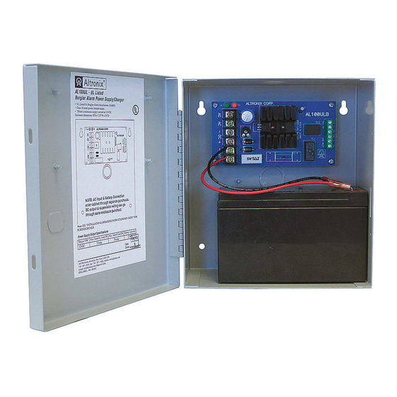
AL100UL
UL Listed Linear Power Supply/Charger
Stand-by Specifications:
Current Draw
Stand-by Time
750mA
4 Hours
Installation Instructions:
Overview:
Specifications:
Battery Backup (cont'd):
• Automatic switch over to stand-by battery when AC fails.
• Low battery disconnect prevents batteries from
deep discharge.
Supervision:
• Low battery and AC fail supervision form "C" contacts
(1A @ 28VDC).
Visual Indicators:
• AC input and DC output LED indicators.
Additional Features:
• Short circuit and thermal overload protection.
• Unit is complete with power supply and enclosure.
• Includes battery leads.
Enclosure Dimensions
8.5" x 7.5" x 3.5" (215.9mm x 190.5mm x 88.9mm).
(H x W x D approx.)
Alarm Time
15 mins.
: