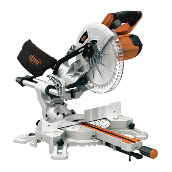
djm direct DJMSL10 Tłumaczenie oryginalnej instrukcji obsługi - Strona 9
Przeglądaj online lub pobierz pdf Tłumaczenie oryginalnej instrukcji obsługi dla Piła djm direct DJMSL10. djm direct DJMSL10 14 stron. 10 single bevel compound sliding mitle saw

A bevel cut is made by cutting across the grain of the workpiece with
the blade angled to the fence and mitre table. The mitre table is set
at the zero degree position and the blade set at an angle between
0°and 45°.
1. Pull on the release knob (2) and lift the saw arm to its full height.
2. Loosen the mitre locks (18) and lifting up the mitre latch (19).
3. Rotate the mitre table (14) until the pointer aligns with zero on the
mitre scale (15).
4. Release mitre latch (19) and retighten the mitre locks (18).
5. Loosen the bevel lock (10) and move the saw arm (1) to the left to
the desired bevel angle (between 0°and 45°). Tighten the bevel lock
(10).
6. Place the workpiece flat on the table with one edge securely
against the fence (12). If the board is warped, place the convex side
against the fence. If the concave side is placed against the fence, the
board could break and jam the blade.
7. When cutting long pieces of timber, support the opposite end of
the timber with side support bars, a roller stand or a work surface
that is level with the saw table.
8. Before turning on the saw, perform a dry run of the cutting
operation to check that there are no problems such as a clamp
interfering with the cutting action.
9. Hold the operating handle (3) firmly and squeeze the switch trigger
(17). Allow the blade to reach maximum speed and slowly lower the
blade into and through the workpiece.
10. Release the switch trigger (17) and allow the saw blade to stop
rotating before raising the blade out of the workpiece. Wait until the
blade stops before removing the workpiece.
Compound mitre cut
If possible, always use a clamping device such as a 'G" clamp to
secure your workpiece.
When cutting your workpiece, keep your hands well away from the
blade area.
Do not remove a cut-off piece on the right-hand side of the blade
using your left hand.
A compound mitre cut involves using a mitre angle and a bevel angle
at the same time. It is used in making picture frames, to cut
mouldings, making boxes with sloping sides and for roof framing.
Always make a test cut on a piece of scrap wood before cutting into
the good material.
1. Pull on the release knob (2) and lift the saw arm to its full height.
2. Loosen the mitre locks (18) and lifting up the mitre latch (19) ..
3. Rotate the mitre table (14) until the pointer aligns with the desired
angle on the mitre scale (15).
4. Release mitre latch (19) and retighten the mitre locks (18).
5. Loosen the bevel lock (10) and move the saw arm (1) to the left to
the desired bevel angle (between 0°and 45°). Tighten the bevel lock
(10).
6. Place the workpiece flat on the table with one edge securely
against the fence (12). If the board is warped, place the convex side
against the fence. If the concave side is placed against the fence, the
board could break and jam the blade.
7. When cutting long pieces of timber, support the opposite end of
the timber with the side support bars, a roller stand or a work surface
that is level with the saw table.
8. Before turning on the saw, perform a dry run of the cutting
operation to check that there are no problems such as a clamp
interfering with the cutting action.
9. Hold the operating handle (3) and firmly and squeeze the switch
trigger (17). Allow the blade to reach maximum speed and slowly
lower the blade into and through the workpiece.
10. Release the switch trigger (17) and allow the saw blade to stop
rotating before raising the blade out of the workpiece. Wait until the
blade stops before removing the workpiece.
To Slide Cut Wide Boards
To slide cut wide boards, Unlock the slide lock knob (22) and allow
the cutting head assembly to move freely.
Setting cutting depth
The depth of cut can be preset for even and repetitive shallow cuts.
1. Slide the stop plate (24) towards the front position.
2. Loosen the lock nut (25) to free the lock knob (23), turn the stop
knob until the cutting head down until the teeth of the blade are at
the desired depth.
3. While holding the upper arm in that position, tighten the lock nut
to secured the stop knob.
4. Recheck the blade depth by moving the cutting head front to
back through the full motion of typical cut along the control arm.
10. Transport
1. Turn off the power tool before any transport and disconnect it
from the power supply.
2. Apply the power tool at least with two people, do not touch the
table extensions.
3. Protect the power tool from knocks, bumps and strong vibrations,
such as during transport in vehi-cles.
4. Secure the power tool against overturning and slid-ing.
5. Never use the safety devices for handling or trans-porting
purposes.
8
