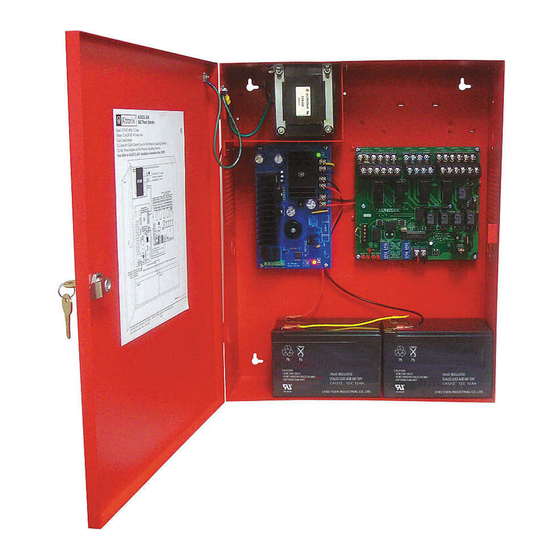
Altronix AL642ULADA Instrukcja instalacji - Strona 5
Przeglądaj online lub pobierz pdf Instrukcja instalacji dla Przedłużacz Altronix AL642ULADA. Altronix AL642ULADA 17 stron. Nac power extenders
Również dla Altronix AL642ULADA: Instrukcja instalacji (17 strony), Instrukcja instalacji (16 strony), Podręcznik aplikacji (8 strony), Podręcznik aplikacji (8 strony)

Note: The AL642ULADA will only synchronize horns, horn/strobes and strobes that contain synchronization capability.
Contact signal manufacturer for more detailed info (see Appendix A.4, pg. 12). The same synchronization mode must be
selected for all outputs.
Amount of Notification Appliances per NAC:
Amseco
Faraday
Gentex
®
*Not to exceed a maximum of 2.5 amp per NAC.
AL842LGK - Logic Board
Terminal Legend Function/Description
These terminals connect to the 24VDC FACP notification appliance circuit outputs. (Class A, Style
Z or Class B, Style W, X, Y) Input trigger voltage is 8-33VDC @ 5mA min. Terminal polarity is
IN1+, IN1 --
shown in alarm condition. During an alarm condition these inputs will cause
IN2+, IN2 --
the selected outputs chosen to drive notification appliances. The designated outputs are set by
(Supervised)
output switches [OUT1 through OUT4] (Output Programming Selection Table, pg. 4). A trouble
condition on an output loop will cause the corresponding input to trip the FACP by opening the
FACP loop. An alarm condition will always override trouble to drive notification appliances.
For Class A, Style Z hookups these terminal pairs return to FACP NAC1 and/or NAC2.
RET1+, RET1 --
For Class B, Style W, X, Y hookups the FACP EOL resistor from the NAC1 and/or NAC2 outputs
RET2+, RET2 --
are terminated at these terminals. Optionally, other notification appliances or additional signaling
(Supervised)
circuit power supplies may be connected to these terminals. If this option is chosen the EOL
resistor must be terminated at the last device.
An open across these inputs, will cause the selected outputs chosen to drive notification appliances.
C "DRY1" NC
C "DRY2" NC
The designated outputs are set by output switches [OUT1 through OUT4] (Output Programming
(Dry input
Selection Table, pg. 4). Note these inputs are unidirectional and will not report a trouble condition
trigger)
to the FACP.
+ OUT1 --
Notification appliances are connected to these regulated outputs (see 42 Application Guide,
+ OUT2 --
pgs. 2-4). Each power limited output will supply 2 amp. Two (2) outputs may be connected in
+ OUT3 --
parallel for a maximum NAC output capability of 4 amp. Total supply current is 6.5 amp
+ OUT4 --
(see note below). Outputs are controlled by designated input 1 [IN1] or input 2 [IN2] (Output
(Supervised)
Programming Selection Table, pg. 4). Maximum line loss or voltage drop (tested with 2.5V).
+ Loop 1 --
+ Loop 2 --
Used for Class A, Style Z hook-ups to terminate loops originating on
+ Loop 3 --
[OUT1], [OUT2], [OUT3], and [OUT4] respectively.
+ Loop 4 --
C "FAULT" NC
An open circuit across this pair of terminals will cause [INP1 and INP2] LEDs to
(Common
simultaneously signal a trouble condition back to the FACP (Typically used to report
trouble input)
AC or BAT Fail). (Fig. 2e, pg. 7).
NC, C, NO
These are dry contact trouble outputs that report any general loop/system trouble conditions.
(Common
(Typically used to trigger a digital communicator or other reporting devices).
trouble output)
(form "C" contact 1 amp / 28VDC 0.35 Power Factor) (Fig. 2, pg. 7).
This separate 1 amp max. auxiliary Special Application Power output circuit is typically used
-- AUX1 +
to power 4-wire smoke detectors. See attached list of devices (Appendix A, pgs. 10-12).
This separate auxiliary regulated power output circuit supplies up to 1 amp during stand-by and
alarm condition. Since this output is not disconnected from its load during AC power failure use
-- AUX2 +
the (Battery Calculation Worksheet, pg. 9) to determine battery size and/or allowable stand-by and
alarm current.
+ DC --
24VDC from power supply.
AL642ULADA
27 per NAC*
39 per NAC*
32 per NAC*
Terminal Identification Table:
System Sensor
®
CooperWheelock
®
32 per NAC*
32 per NAC*
- 5 -
