Custom Dynamics Road Glide CD-RG-TS-15-B Instrukcje instalacji - Strona 2
Przeglądaj online lub pobierz pdf Instrukcje instalacji dla Akcesoria motocyklowe Custom Dynamics Road Glide CD-RG-TS-15-B. Custom Dynamics Road Glide CD-RG-TS-15-B 2 stron. Led turn signals
Installation (Continued):
9.
Remove both the left and right OEM turn signal housings from
the outer fairing by removing the two ¼" allen head socket
bolts on the back side of each turn signal.
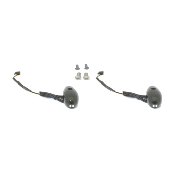
10. Install the new right front turn signal and attached gasket by
routing the wire and plug through the hole in the fairing and
through the clip.
11. Align the locating pin on the backside of the new turn signal
unit with the hole on the plastic mount. Place a drop of supplied
Loctite on threads of supplied 5/16-18 socket head screw,
tighten securely.
12. Repeat steps 10 and 11 for the left side.
13. Reinstall the outer fairing using the original hardware from
steps 6 and 7
14. Route the wires from each turn signal to the OEM connectors
(unplugged in step 3) and plug in making sure the left turn
signal is plugged into the OEM connector with a purple wire
and the right turn signal is plugged into the OEM connector
with a brown wire.
15. Place a drop of supplied thread locker on threads of supplied
1/4x20 button head screws. Install and tighten from the outside
of each turn signal.
16. Reinstall speaker grilles by applying light pressure. They
should snap into place.
17. Reinstall factory vent by snapping it into place.
18. Reinstall windshield using original hardware.
19. Perform a BCM sync by turning key on, turn 4 way hazards on,
turn key off. Allow hazards to run for 3-4 minutes. Turn Key on,
Turn Hazards off, Turn Key off.
20. Test operation of running and turn signal lights.
Questions? Call us at: 1 (800) 382-1388
Installation Instructions - Page 2
M-TH 8:30AM-5:30PM / FR 9:30AM-5:30PM EST
10
20
09-2016SM