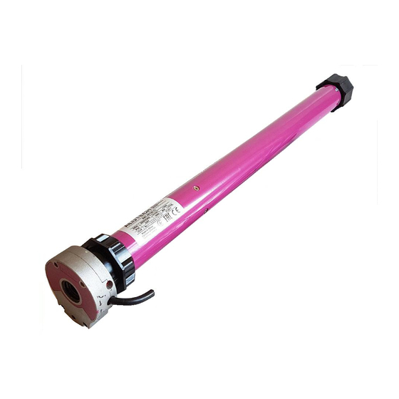
Alutech AM0 Series Instrukcja obsługi - Strona 11
Przeglądaj online lub pobierz pdf Instrukcja obsługi dla Silnik Alutech AM0 Series. Alutech AM0 Series 17 stron. Tubular motors

27
24
3. Installation
The roller shutter should be in good condition and suitable for automation; awnings of
roller shutter should be freely moved along guide slides.
Free access to the place of the motor installation should be provided.
When installing the motor at the height less than 2.5m all the moving parts should be
protected against ingress of foreign objects.
Prior to installation all the unnecessary items (cables, wires, ropes, etc.) should be re-
moved and unused equipment should be turned off.
The motor control switch should be located in easily visible location of the shutter, at
safe distance from moving parts, at the height no less than 1.5m.
The electrical network should be provided with protective grounding. The section of
electrical network to which the motor is to be connected, should be equipped with pro-
tective device. The distance between terminals in the circuit breaker is no less than
3mm.
Attention! It is not allowed to connect parallel several motors to the single circuit
breaker. It is not allowed to connect several circuit breakers to the single motor. The
circuit breaker should be with lockout device of simultaneous switching on for the oppo-
site directions of the motor shaft rotation.
When using the motor outdoors the electrical cables should be in the special piping.
When mounting the power cable should be downward directed, or the cable should be
laid with the loop downward directed to avoid the penetration of the condensate (wa-
ter) on the motor.
Attention! During installation it is forbidden to hammer the motor in the shaft, drill
and screw in the screws in the shaft throughout the length of the tubular motor.
The length of metal-ware (screws, rivets, etc.) should be chosen so that after installa-
tion they do not touch the tubular motor, do not prevent mounting of the motor and
use the manual emergency control.
This instruction is to be considered as an example since the installation position of the
motor and its components may be different. The task of the wireman is to choose the
most suitable solution.
General Recommendations (Fig. 6-11, 13):
•
The ring 2 (Fig. 6-10) is mounted on the head part of the motor 1 against stop so the projec-
tion on the motor and the groove on the ring are aligned. The adapter 3 is installed on the
motor output shaft;
•
Install the motor into octagonal shaft so that the ring is fully seated in the shaft;
•
Perform fixation of the adapter to the shaft with self-tapping screw or rivet at the distance
L2 (Table 1);
•
Using mounting fastener 4 secure the head part of the motor to the side cover of the shut-
ters. The motor should be installed horizontally, perpendicular to the guides of the shutters
(perpendicular to mounting fastener);
•
For the motors of AM1-PP and AM2-PP series install the loop (Fig. 13) of the manual emer-
gency control mechanism;
•
Perform the electrical connections (Fig. 11).
L1
L2
Fig.5 – Dimensions of AM2-PP series motors
36
11
110
61
