DLS 125 Szybki start - Strona 2
Przeglądaj online lub pobierz pdf Szybki start dla Pompa wodna DLS 125. DLS 125 2 stron. Car audio speakers
Również dla DLS 125: Podręcznik (4 strony), Instrukcja obsługi (4 strony), Szybki start (2 strony), Skrócona instrukcja obsługi (4 strony)
This brief instruction of mounting the FlexxPump 125 DLS
addresses to experienced users. Please visit
www.dls-schmiersysteme.de to download the complete user
manual including all safety instructions.
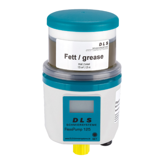
1. Product details FlexxPump 125 DLS
0
1
5
4
2
3
No.
Description
0
FlexxPump 125 DLS
1
LCD
2
Electric interface M12x1
3
Lubricant outlet / M16 male thread for bottom mounting
4
M5 female thread for bottom mounting
5
Serial number
6
M5 female thread for rear mounting
7
Cartridge sensor
8
Lubricant inlet with thread for cartridge
9
Nameplate with designation and CE mark
2. Technical data
Housing
Mounting options
backside: female thread M5 (2x)
bottom: f. thread M5 (1x), m. thread G1/4(1x)
Max. Torque mounting
3
Mounting position
upright
Operating temperature
-10 bis +60
Lubricant and hydraulic
Number of lubrication
up to 4 by using splitters*
points
up to 10 by using progressive distributors*
Max. Pressure
50 (-10 % / +15 %)
Grease delivery
Per stroke 0,15
Electrics
Operating voltage
24 (20...28)
Protection
0,75 (slow blow)
Protection class
IP 54
* The stated value is down to the individual application and may
extensively differ in some cases (depending on the lubricant and further
conditions).
3. Mounting
6
1.
Remove the yellow protective cap from the top of the lubricant
7
inlet of the FlexxPump 125 DLS.
2.
Unscrew the yellow protective cap counterclockwise from the
8
lubricant outlet on the bottom of of the FlexxPump 125 DLS.
Remove the black protective cap from the electrical interface
on the bottom of the FlexxPump 125 DLS.
9
3.
To connect the FlexxPump 125 DLS with an external power
supply system add a proper connecting cable to the electrical
interface on the bottom of the FlexxPump 125 DLS.
4.
Turn the cap on the lubricant cartridge counterclockwise and
pull it off.
5.
Place the full lubricant cartridge with the lable up front on the
FlexxPump 125 DLS. Turn the lubricant cartridge
se onto the FlexxPump 125 DLS.
4. Commissioning
1.
Mechanical fastening
Fix the FlexxPump 125 DLS mechanically through the M5
female threads or through the
Nm
outlet. Pay particular attention to the maximum tightening
torques permissible for the M5 female threads!
2.
Electrical connection
°C
3.
Power on
4.
Execute FIL function
5.
Hydraulic connection
Connect the consumer hydraulically to the FlexxPump 125 DLS.
If you connect tubes to the FlexxPump 125 DLS, make sure that
bar
tubes and connectors are installed tightly, cleanly and correctly.
cm³
Ideally, use tubes prefilled with the appropriate lubricant.
5. Operation and settings
V
5.1 Default settings, operating mode: impulse mode PUL
Impulse mode PUL enables embedding the FlexxPump 125 DLS in
A
an external control (PLC) to command and control the device. The
number of strokes (one stroke=0.16 cm³) dispensed now depend on
the PLC's signals.
LCD
twice
DANGER
Damaged or flawed electrical connections or un-
licensed hot components lead to heavy injuries or
even death.
male thread of the lubricant
G1/4
5.2 Input and output signals
2
3
4
1
The FlexxPump 125 DLS can be switched off completely by switching
off the supply voltage.
The output signal at PIN 4 can be tapped for further processing
(e.g. indicator light or external control). The maximum permissible
current output must not exceed
Imax < 20mA. No inductive load (e.g. relay) may be connected!
In pulse control mode the FlexxPump 125 DLS operates as a pulse-
controlled lubrication system only if unalterable input signals (high
level) are transmitted from the PLC to the FlexxPump 125 DLS via
clockwi-
PIN 2 in a defined sequence. the FlexxPump 125 DLS signals the
respective status to the PLC via high/low levels which can be tapped
off at PIN 4.
To operate the FlexxPump 125 DLS via an external controller
(PLC) in pulse control mode a program corresponding to the
communication protocol must be created in the PLC.
PIN2: Input signal PLC FlexxPump 125 DLS
The FlexxPump 125 DLS provides the following unalterably defined
control signals (input signals) which must be transmitted from the
PLC to the FlexxPump 125 DLS via PIN 2 of the electrical M12x1
interface as high level (+24 V DC).
The control signals must be generated as high level (+24 V) by the
external controller (PLC) over certain times with a tolerance of +/-
0.1 seconds.
Signal length in
Description
seconds
2 high
Signal 2 seconds
12 high
Signal 12 seconds
14 high
Signal 14 seconds
PIN assignment - time control
PIN
Assignment
Colour
1
+24 V DC
brown
2
unallocated
white
3
ground
blue
4
output signal
black
Type: M12x1 female connector; 4-pin; A-coded
Function
1 stroke
FIL-Function
Error acknowledgement