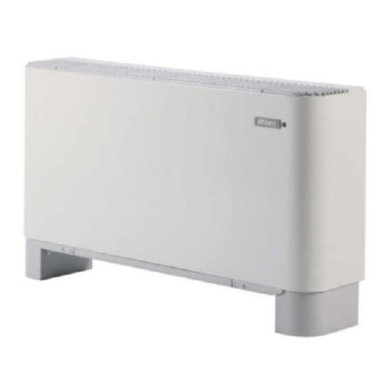
AERMEC FCS 62 Podręcznik użytkownika - Strona 9
Przeglądaj online lub pobierz pdf Podręcznik użytkownika dla Chiller AERMEC FCS 62. AERMEC FCS 62 15 stron. Fan coil
Również dla AERMEC FCS 62: Wskazówki dotyczące użytkowania i instalacji (20 strony)

SCHEMI ELETTRICI • WIRING DIAGRAMS • SCHEMAS ELECTRIQUES • SCHALTPLÄNE • ESQUEMAS ELÉCTRICOS
LEGENDA • READING KEY • LEGENDE • LEGENDE • LEYENDA
IG
= Interruttore generale • Main switch • Interupteur général
Hauptschalter • Interruptor general
M
= Morsettiera • Terminal board
Boitier • Klemmleiste • Placa de bornes
MV
= Motore ventilatore • Fan motor • Moteur ventilateur
Ventilatormotor • Motor del ventilador
SA
= Sonda ambiente • Room sensor • Sonde ambiante
Raumtemperaturfuhler • Sonda ambiente
SC
= Scheda di controllo • Electronic control board
Platine de contrôle • Steuerschaltkreis
Tarjeta electrónica de control
VCF = Valvola solenoide • Solenoid valve
Vanne solenoide • Magnetventil • Válvula solenoide
FCS - ACB Meuble haut avec thermostat électronique à fonctions réduites
FCS - ACB Standgerät mit elektronischer Thermostat mit eingeschränkten Funktionen
M
1
2
VCF
FCS - ACB Mobile alto con termostato elettronico a funzioni ridotte
FCS - ACB Tall cabinet with reduced-function electronic thermostat
GR
BL
NE MA RO
3
4
5
6
7
8
9 10
BL
NE MA RO
MV
~
1
Sez. 1,5 mm 2
L
N
IG 2A
230V 50Hz
= Componenti non forniti • Components not supplied
Composants non fournis • Nicht lieferbare Teile
Componentes no suministrados
= Componenti forniti optional • Optional components
Composants en option • Optionsteile
Componentes opcionales
= Collegamenti da eseguire in loco
On-site wiring
Raccordements à effectuer in situ
Vor Ort auszuführende Anschlüsse
Cableado in situ
BL
= Blu • Blue • Bleu • Blau
MA
= Marrone • Brown • Marron • Braun
NE
= Nero • Black • Noir • Schwarz
RO
= Rosso • Red • Rouge • Rot
SC
N
N
PE
L
Y1
V3
V2
V1
M1
M2
SA
PE
INT
EXT
DL1
JP1
PT1
SA
9
