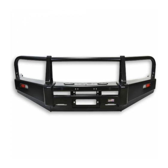
Dobinsons BU59-3696 Skrócona instrukcja obsługi - Strona 5
Przeglądaj online lub pobierz pdf Skrócona instrukcja obsługi dla Akcesoria samochodowe Dobinsons BU59-3696. Dobinsons BU59-3696 9 stron. Bullbar for toyota landcruiser 200 series facelift models

14. You may have to cut and bend the centre
brace to allow clear the winch drum as seen
below.
15. This may require the clutch handle and gear-
box housing to be rotated forward one or 2
bolt holes to allow easy access through the
bulbar holes. See instructions in winch user
manual.
16. Determine where the winch control box will
be located and mount the control box. See
instructions in winch user manual for control
box mounting options. If mounting to the top
of the bullbar using the supplied bracket,
check clearance of control box to grill and also
check where the wires will route as if the
wires are passing through the holes in the top
of the bullbar the control box may not be able
to be wired until the bullbar has been fitted as
below.
17. Wire the winch up as per the winch
instruction manual and bolt the winch to the
mounting bracket, ensure the mounting bolts
are not too long and tighten correctly. Route
the wires and connect to battery and also
route the breather hose.
18. Reinstall the grill and top cover.
19. Unwind some cable from the winch, and pass
the cable through the fairlead hole in the
bullbar and through the roller fairlead. This
Dobinsons Springs and Suspension
may require removing a circlip from the
fairlead and re installing once the cable is
passed through.
20. Install the roller fairlead into the bulbar.
21. Check the poly bulbar over riders, fog light
and top loop bolts are tight (Do not over
tighten the stainless steel loop mounting
bolts. Do not over tighten the poly bullbar
over riders as they will pull the over riders out
of shape).
22. Fit the rubber under headlight inserts to the
bullbar, do not over tighten the bolts.
23. With help, fit the bulbar and loosely fit the
mounting hardware supplied.
24. Check for clearance on the winch control box
and access for the clutch handle and winch
controller socket.
25. Align the bulbar to the vehicle leaving at least
a 13mm gap at the bullbar wing to the bottom
of the quarter panel and tighten the mounting
bolts.
26. Once happy with the alignment of the bullbar
drill 2 x 8mm pinning holes on each side of the
bullbar drilling through both the mounting
bracket mounting plate and bullbar mounting
plate. Fix with 8mm bolts and nyloc nuts to
keep the bullbar in its position.
27. Wire up the lights. Using a multimeter or test
light first locate the earth wire, parker positive
and indicator positive wires from the wiring
on the back of the original vehicle lights on
each side.
www.dobinsonsprings.com
