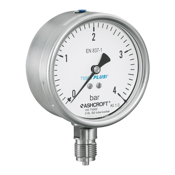
Ashcroft T6500-kf Instrukcja instalacji i konserwacji - Strona 2
Przeglądaj online lub pobierz pdf Instrukcja instalacji i konserwacji dla Przyrządy pomiarowe Ashcroft T6500-kf. Ashcroft T6500-kf 6 stron. Pressure gauges with switching contacts

Installation and Maintenance Instruction for
T5500/T6500 Pressure Gauges
with switching contacts
1.3
Limits of liability
Refer to Ashcroft standard terms of sale for limits of liability.
1.4
Copyright
This Operating Manual may only be copied and passed on
as a complete document without the special permission of
the publisher.
1.5
Warranty
For the product described here, we offer a warranty
pursuant to our General Terms and Conditions on Delivery
and Payment, Section 6: Liability for Defects.
1.6
Manufacturer's address, customer services
Ashcroft Instruments GmbH
Tel.: +49 (0) 2401/808-888
Max-Planck-Strasse 1
Fax.: +49 (0) 2401/808-999
D-52499 Baesweiler
E-mail: [email protected]
Germany
Web: www.ashcroft.eu
2 Safety
2.1
General sources of hazards
Pressure gauges are pressurized parts where failure can
result in hazardous situations. The selection of pressure
gauge should be made in accordance with the rules set out
in EN 837-2, selection of contacts i
2.2
Use in accordance with intended purpose
The devices are only to be used for the intended purpose as
described by the manufacturer.
The devices are used for direct display of overpressure,
vacuum and compound pressure.
The integrated switching elements are magnetic spring
contacts or inductive proximity switches with a groove
design, supplied by isolating switch amplifiers. If the set
limit values are exceeded, the output circuits are opened or
closed.
For each use scenario, the corresponding set-up regulations
must be respected. The use in explosion risk areas is not
permitted (use T5500-KF/T6500-KF with ATEX approval
instead).
2.3
Operator's responsibility
Safety instructions for proper operation of the device must
be respected. They are to be provided by the operator for
use by the respective personnel for installation, servicing,
inspection and operation. Risks from electrical energy and
from the released energy of the medium, from escaping
media and from improper connection of the device must
be eliminated. The details for this are to be found in the
corresponding applicable set of regulations, such as DIN
EN, UVV (accident prevention regulations) and in sector-
specific instances of use (DVWG, Ex-. GL, etc.) the VDE
guidelines and the regulations supplied by local utilities
companies.
The device must be taken out of service and secured
against inadvertently being restarted, if the presumption is
that risk-free operation is no longer possible (see Chapter 9:
Faults).
Ashcroft Instruments GmbH
Deutschland / Germany
Max-Planck-Str. 1
D-52499 Baesweiler
Tel.: +49 (0) 2401 808-0
©2018 Ashcroft Instruments GmbH IM-T5500KF-EN Rev. A 11/18
P/N 095I111-01EN
All specifications are subject to change without notice. All sales subject to standard terms and conditions.
ashcroft.eu
For more information on support and
local partners please visit our web
page at ashcroft.eu or follow the
QR-Code
Altering the gauge by the customer is not permitted.
This also applies to installation of spare parts. Possible
conversations or alterations may only be carried out by the
manufacturer.
The operational safety of the device is only guaranteed
where it is used for its intended purpose. The specification
of the device must be adapted to the medium used in the
plant. The limit values indicated in the technical data must
not be exceeded.
The safety information detailed in this Operating Manual,
existing national regulations for accident prevention, and the
operator's internal regulations regarding working, operations
and safety must be respected.
The operator is responsible for all specified servicing,
inspection and installation works being carried out by
authorized and qualified specialists.
2.4
Staff qualifications (target group assessment)
The device may only be installed and started up by
specialist staff who are familiar with installation, start-up and
operation of the product.
Specialist staff are people who are able to assess the work
assigned to them on the basis of their specialist training,
their knowledge and experience and their knowledge of the
relevant standards, and can identify possible risks.
2.5
Signs/Safety markings
The pressure gauge and its surrounding packaging
carry markings. These markings show the article number,
measurement range, contact function, wiring, maximum
overload and manufacturer. The pressure gauge can be
provided with additional signs and safety markings advising
on special conditions:
•
Advice on the filling liquid
•
Advice on calibration
•
Safety marking pursuant to EN 837-1
•
Oil-can deleted (if oxygen is used)
•
Silicone-free (for use in the automotive industry)
2.6
Safety equipment
This device is fitted with a rear wall or plug capable of being
blown out. For a description, please refer to Chapter 5.3.4
2.7
Environmental protection
This device may optionally contain a filling liquid (e.g. white
oil). The provisions set out in the REACH regulation on
production and use of chemicals are to be respected, and
the relevant safety data sheets from the manufacturers of
the chemicals are available on our website for download.
Regarding the electric contacts are offered: The
provisions set out in the WEEE regulation EU directive
2012/19/EC on electrical and electronically equipment are
to be respected, and the products are registered at the EAR
under the number DE 26646349.
Page 2
