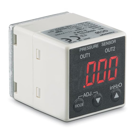
Ashcroft GC30 Skrócona instrukcja obsługi - Strona 6
Przeglądaj online lub pobierz pdf Skrócona instrukcja obsługi dla Akcesoria Ashcroft GC30. Ashcroft GC30 7 stron. Ultra-compact digital
differential pressure transducer
Również dla Ashcroft GC30: Instrukcja instalacji i konserwacji (20 strony)

Product Information Page
Switching Verification:
Ensure switches wiring per figure 3 diagram or installation and maintenance instructions. Switching
verification can be tested during measurement mode or loop check. Change loop check value or apply
equivalent pressure (see results below for reference).
Output 1 Switch Set Point to Activate Audible Alarm When Differential Pressure Reaches .500 IWC
For test purpose a 290 ohms resistor shall
be used as the switch load (wire switch per
manual instructions or figure above).
Press the Up or Down arrow until .200 is
displayed or apply .200 IWC.
Output 1 switch in normal state (OFF).
Place voltmeter leads across resistor and
verify voltage reading (0 V dc).
Press the Up arrow until .500 is displayed or
increase pressure to .500 IWC.
Output 1 switch turns ON.
Verify voltmeter reading (28 VDC).
External relay energizes.
Relay normally open closes
Audible alarm turns ON.
Press the Down arrow until .200 is displayed
or decrease pressure to .200 IWC.
Verify voltage reading (0 V dc).
Output 1 switch changes to normal state
(OFF).
Audible alarm turns OFF.
All specifications are subject to change without notice.
All sales subject to standard terms and conditions.
© 2017 Ashcroft Inc.
ashcroft.com
info@ ashcroft.com
1.800.328.8258
Rev. A 02/17, Page 6 of 7
