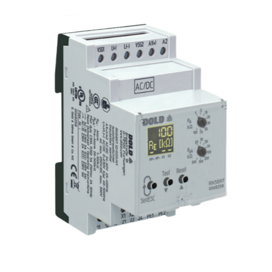
DOLD VARIMETER IMD RP 5898 Tłumaczenie oryginalnych instrukcji - Strona 6
Przeglądaj online lub pobierz pdf Tłumaczenie oryginalnych instrukcji dla Urządzenia przemysłowe DOLD VARIMETER IMD RP 5898. DOLD VARIMETER IMD RP 5898 17 stron. Insulation monitor
Również dla DOLD VARIMETER IMD RP 5898: Tłumaczenie oryginalnych instrukcji (8 strony), Technika monitorowania (12 strony), Technika monitorowania (12 strony)

Technical Data
Measuring ciruit L(+)/L(-) to PE1/PE2 (with coupling device)
Nominal voltage U
:
N
Max. max. voltage range U
: AC 0 ... 250 V
N
Frequency range:
Max. line capacitance:
Internal resistance (AC / DC): > 90 kΩ
Measuring voltage:
Max. mesured current (R
= 0): < 1,10 mA
E
Response inaccuracy:
Response value hysteresis:
On delay
At C
= 1µF,
E
response value ≤ 100 kΩ,
of ∞ to 0.5 * response value:
R
E
At C
= 1µF,
E
response value > 100 kΩ,
of ∞ to 0.5 * response value:
R
E
Measuring time:
At C
= 1 ... 5 µF
E
Min. operate time:
Response value
Adjustable via Modbus
Pre-warning "R
":
pA
Alarm "R
":
A
Response value broken
wire detection L(+)/L(-):
Response value broken
wire detection PE1/PE2:
Meas. ciruit L(+)/L(-) to PE1/PE2 (with coupling device RL / RP 5898)
Nominal voltage U
:
N
Max. max. voltage range U
: AC 0 ... 440 V
N
Frequency range:
Max. line capacitance:
Internal resistance (AC / DC): > 240 kΩ
Measuring voltage:
Max. mesured current (R
= 0): < 0.40 mA
E
Response inaccuracy:
Response value hysteresis:
On delay
At C
= 1µF,
E
response value ≤ 100 kΩ,
of ∞ to 0.5 * response value:
R
E
At C
= 1µF,
E
response value > 100 kΩ,
of ∞ to 0.5 * response value:
R
E
Measuring time:
At C
= 1 ... 5 µF
E
Min. operate time:
Response value
Adjustable via Modbus
Pre-warning "R
":
pA
Alarm "R
":
A
Response value broken
wire detection L(+)/L(-):
Response value broken
wire detection PE1/PE2:
Max. wire length
between insulation monitor
and coupling device:
AC / DC 0 ... 230 V
DC 0 ... 300 V
DC oder 40 ... 1000 Hz
5 µF
Ca. ± 90 V
± 15 % ± 1,5 kΩ
IEC 61557-8
Approx. + 25 %; min. + 1 kΩ
≤ 1 s
< 2 s
< 5 s
> 0.2 s
In the range of 1 ... 500 kΩ in 1 kΩ steps
In the range of 1 ... 500 kΩ in 1 kΩ steps
> Approx. 90 kΩ
> Approx. 0.5 kΩ
RL 5898
RP 5898
AC 0 ... 400 V
AC 0 ... 690 V
DC 0 ... 500 V
DC 0 ... 1000 V
AC 0 ... 760 V
DC 0 ... 550 V
DC 0 ... 1100 V
DC or 40 ... 1000 Hz
5 µF
Approx. ± 90 V
± 15 % ± 1.5 kΩ
IEC 61557-8
Approx. + 25 %; min. + 1 kΩ
≤ 1 s
< 2 s
< 5 s
> 0.2 s
In the range of 1 ... 500 kΩ in 1 kΩ steps
In the range of 1 ... 500 kΩ in 1 kΩ steps
> Approx. 500 kΩ
> Approx. 0.5 kΩ
< 0.5 m
Technical Data
Auxiliary voltage input A1(+)/A2
Nom. Voltage
Voltage range
AC 19 ... 68 V
AC/DC 24 ... 60 V
DC 19 ... 96 V
AC 70 ... 276 V
AC/DC 100 ... 230 V
DC 80 ... 300 V
*
W = Permitted residual ripple of auxiliary supply
)
Nominal consumption:
DC 12 V, 24 V, 48 V:
AC 230 V:
Control input X1/X2 for external combined Test-/Reset-Taste
Current flow:
No-load operation voltage
X1 to X2:
Permissible wire length:
Activat. time t for test signal: 1.5 s < t < 10 s
Activat. time t for reset signal: t < 1.5 s
Activation time t for stop
of the measuring function:
Outputs
Indicator contact:
Thermal current I
:
th
Switching capacity
To AC 15:
NO contact:
NC contact:
To DC 13:
Electrical life
At 5 A, AC 230 V:
Short circuit strength
Max. fuse rating:
Mechanical life:
General Data
Operating mode:
Temperature range
Auxiliary voltage
AC/DC 24 ... 60 V:
Auxiliary voltage
AC/DC 100 ... 230 V:
Storage:
Altitude:
6
Frequency range
45 ... 400 Hz; DC 48 % W*
≤ 5 %
W*
)
45 ... 400 Hz; DC 48 % W*
≤ 5 %
W*
)
Max. 3 W
Max. 3.5 VA
Approx. 3 mA
Approx. 12 V
< 50 m
t > 10 s
2 x 1 changeover contact for Alarm (K1)
and Pre-Alarm (K2)
energized or de-energized on trip
(programmable)
Max. 4 A
(see also temperature range operation)
5 A / AC 230 V
IEC/EN 60947-5-1
2 A / AC 230 V
IEC/EN 60947-5-1
2 A / DC 24 V
IEC/EN 60947-5-1
1 x 10
switching cycles
5
4 A gG / gL
IEC/EN 60947-5-1
50 x 10
switching cycles
6
Continuous operation
- 40 ... + 60 °C
- 40 ... + 70 °C (Device mounted with
min. 1 cm distance to
adjacent devices or
device with max. 2 x
0.5 A contact current)
- 40 ... + 60 °C
- 40 ... + 70 °C (Device mounted with
min. 1 cm distance to
adjacent devices and
device with max. 2 x
0.5 A contact current)
- 40 ... + 70 °C
≤ 2000 m
IEC 60664-1
12.07.22 en / 604A
)
)
