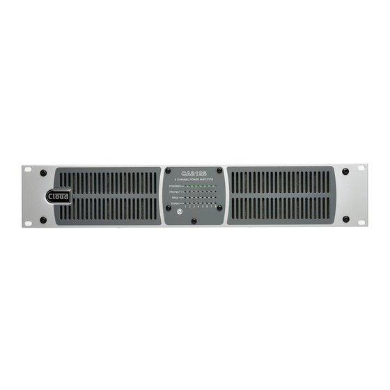
Cloud CA2500 Instrukcja instalacji i obsługi - Strona 16
Przeglądaj online lub pobierz pdf Instrukcja instalacji i obsługi dla Wzmacniacz Cloud CA2500. Cloud CA2500 19 stron.
Również dla Cloud CA2500: Biuletyn techniczny (13 strony)
C l e a r l y b e t t e r s o u n d
High Pass Filters
Most transformers fitted to 70/100 V-line speakers exhibit
core saturation when fed with high-level signals at low
frequencies. Transformer saturation creates unpleasant
distortion and stresses the system. To counteract this, a
correctly configured high pass filter is an essential part of
any line distribution system. CA Series amplifiers have a high
pass filter in each channel, selectable via the 65Hz FILTER DIP
switch on the rear panel
5
CA6160 and CA8125, this is a dedicated 2-, 4-, 6- or 8-pole
switch: on Model CA2250, output mode selection is made
using poles SW1 and SW2 of the single 8-pole DIP switch.
(The first example shown below is for the 4-channel CA4250;
the principle is identical across the range.)
Filter off
(flat response)
1
ON
(CA4250)
CH2 Hi-Z/Lo-Z
CH1 Hi-Z/Lo-Z
CH2 4Ω /70V or 8Ω /100V
CH1 4Ω /70V or 8Ω /100V
CH2 INPUT ROUTING
APD ON/OFF
CH2 65Hz HPF
CH1 65Hz HPF
Filter off
(flat response)
1
2
3
ON
(CA2250)
16
CA Series Installation & User Guide v1.0
. On Models CA2500, CA4250,
65Hz FILTER
OFF
Filter on
(LF removed)
2
3
4
ON
Filter on
(LF removed)
4
5
6
7
8
Low impedance operation
In low-impedance mode, the output stage may be optimised
for use with loads of either four or eight ohms with the
SPEAKER LOAD 4 Ω/70V / 8 Ω/100V DIP switch
4 Ω setting (switch UP) the load impedance must not be less
than four ohms, and in the 8 Ω setting (switch DOWN) the
load impedance must not be less than eight ohms. However,
higher impedances may be driven in both cases, though the
maximum power output of the amplifier channel will not be
available.
Check the impedance of the loudspeakers to be driven by
the amplifier; if using multiple loudspeakers, employ series/
parallel wiring as appropriate to ensure the combined
impedance is not less than the impedance set with switch
The power capability of an amplifier in low impedance mode
should be taken to be the nominal channel power level for
the particular amplifier model, assuming the load impedance
matches that set by switch
channel of a CA8125 should be considered to be loading its
power supply with 125W.
Level Control
Control of audio level in each channel is provided by the
rear panel preset rotary LEVEL control
appreciated that this adjusts the signal level feeding the
amplifier power stage and is thus essentially an output level
control, not an input level or sensitivity control. The preset
should be adjusted using a trim tool or small screwdriver.
Zero output is obtained with the control fully anti-clockwise.
Full output level is with the control fully clockwise; at this
setting the maximum output power (70 V
high impedance mode) will be produced for an input signal
level of 0.775 V
(0 dBu).
rms
We recommend that the level for each channel should be
set after installation is complete by commencing with the
LEVEL controls at minimum. Installers should ensure that
adequate, but not excessive sound levels are achieved with
the programme material that will be used in practice.
. In the
7
. For example, a low-impedance
7
. It should be
3
or 100 V
rms
rms
.
7
in