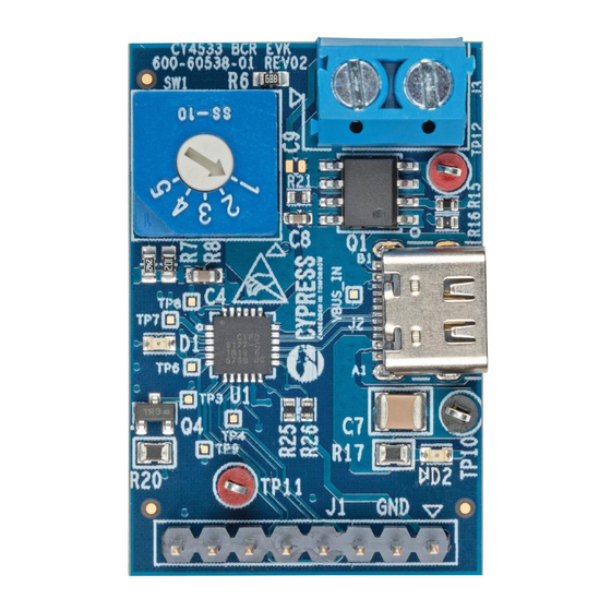
Cypress EZ-PD CY4533 Podręcznik - Strona 18
Przeglądaj online lub pobierz pdf Podręcznik dla Płyta główna Cypress EZ-PD CY4533. Cypress EZ-PD CY4533 20 stron. Barrel connector replacement (bcr) evaluation kit

4.
Open the analyzer software and start a capture.
5.
Connect a USB Type-C power adapter to the Type-C receptacle of the analyzer. You will see USB Power Delivery
packets on the analyzer software.
Each USB Type-C power adapter will advertise a list of voltage and current combinations (called PDOs). The BCR
controller will select the best PDO based on a set of rules described in
from Power Adapter
.
In short, the VBUS_MAX rotary switch governs the highest voltage that the BCR device will try to request. If that voltage is
unavailable, it looks for the next highest voltage, and so on.
To test this, perform the following steps on the demo setup:
1.
Set the VBUS_MAX Rotary Switch (SW1) to position 1. Verify that the multimeter displays a voltage between 4.5V
and 5.5V.
2.
Set the VBUS_MAX rotary switch (SW1) to position 2. Verify that the multimeter displays a voltage between 8.55V
and 9.45V. If the power adapter does not support this voltage, you will see ~5V.
3.
Similarly loop through all voltages and verify that the multimeter reads VBUS_MAX ± 5%, if the power adapter
supports that voltage.
3.3 Behavior under Mismatching Capabilities
If the attached USB Type-C power adapter can supply a VBUS voltage within VBUS_MIN and VBUS_MAX limits, the CY4533
EVK will turn the load switch ON to pass the voltage onto the terminal block J3.
On the other hand, if the attached power adapter does not have a matching voltage/current combination, the BCR device
will indicate a capability mismatch to the power adapter and will turn the load switch OFF. See
Selectors
for details.
Under mismatch conditions, the red FAULT LED D1 turns ON and the VBUS voltage is routed to the VSAFE5V test point
(TP12). See
FAULT LED and Safe 5V Load Switch
CY4533 EZ-PD™ BCR Evaluation Kit Guide, Document Number: 002-25263 Rev. *B
Changing VBUS Voltage and Current Requested
for details.
Kit Operation
VBUS Voltage and Current
18
