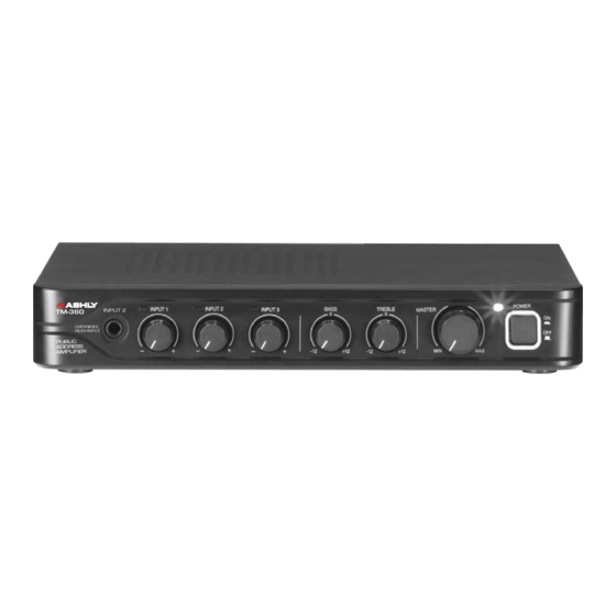
Ashly TM-360 Instrukcja obsługi - Strona 6
Przeglądaj online lub pobierz pdf Instrukcja obsługi dla Wzmacniacz Ashly TM-360. Ashly TM-360 16 stron. Public address amplifier
Również dla Ashly TM-360: Instrukcja obsługi (16 strony), Skrócona instrukcja obsługi (1 strony), Skrócona instrukcja obsługi (1 strony), Skrócona instrukcja obsługi (1 strony), Skrócona instrukcja obsługi (1 strony)

Operating Manual - TM-360 Public Address Amplifier
(rear panel features cont. . . .)
5) Mix Configuration DIP Switches
Switches 1, 2, and 3: Zone 2 Assign
These assign each input to Zone 2 output, post-level control. There is no effect to the main output mix.
Switches 4-5: VOX Trigger -
The TM-360 has the ability to trigger a mute on channel 2 or 3 from the presence of an audio signal
on channel 1 or 2. This is called voice operated switching, or VOX. Input 2 has priority over input 3,
and input 1 has priority over input 2. Input 1 also has the ability to use a contact closure trigger such
as a mic push-to-talk switch for priority muting of channel 2. Additionally, input 1 can be set to have
priority over both inputs 2 and 3 together (see switch 6).
The TM-360 has audio detecting LEDs on each input. When the VOX TRIG switches are set to ON for
inputs 1 or 2, the same signal level which activates the LED is used as the VOX trigger. VOX mutes
the dependent channel until the trigger signal falls back below the LED threshold. Each input features
a rear panel gain trim that first optimizes the overall input sensitivity for each input, but can also serve
to fine-tune the sensitivity of the signal detector which creates the VOX trigger point for each input.
Switch 6: Mute Link 2&3
When this switch is turned on, it sets the channel 1 VOX trigger or manual mute contact closure to
mute both channels 2 and 3. If only channel 2 is to be affected, leave it off.
Switch 7: Low-Cut Filter
This switch turns on a 400Hz 6dB/oct low-cut filter affecting the main and PRE outputs but not the
zone 2 outputs. This is useful for providing the proper EQ for paging horns.
Switch 8: CH 1 MIC Phantom Power
This provides +18V phantom power to input 1 for use with condenser and electret microphones.
6) Input 3 Connectors
3.5mm Euroblock connectors and summed stereo RCA jacks are used for input 3. If wiring an unbal-
anced input signal into a balanced Euroblock input, be sure to ground the (-) input pin.
7) Input 3 Gain Control
Input 3 gain trim range is adjustable from -10dB to +10dB
6
