Asian Phoenix Resources MHG-T16 Instrukcja obsługi i konserwacji - Strona 8
Przeglądaj online lub pobierz pdf Instrukcja obsługi i konserwacji dla Falownik Asian Phoenix Resources MHG-T16. Asian Phoenix Resources MHG-T16 17 stron. Micro-hydroelectric generator

The top of the penstock is typically placed not at the bottom but some way up the
forebay wall so that the bottom of the forebay acts as a sink for rotting leaf litter,
deposited sand and mud etc. This sink may need periodic cleaning out. Another good
idea is to cover the end of the penstock with a piece of wire mesh (debris screen) to
keep leaves etc. from flowing in and clogging the turbine. See Appendix B for the
ideal forebay design.
SYSTEM INSTALLATION
Mechanical Aspects
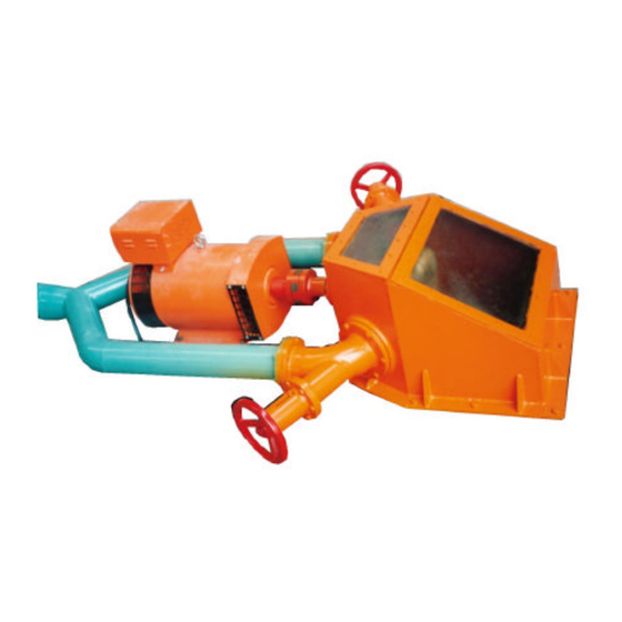
After locating a suitable site and completing the civil works, your PowerPal is ready
for installation. To do this:
1. Bolt the turbine to a turbine stand or base which allows at least 500mm clearance
between the turbine and the ground. This clearance is required to prevent
splashback that will disrupt turbine performance. The turbine stand should be
made from concrete with the six M24 foundation bolts embedded.
2. Attach the gate valve to the nozzle injector pipe followed by a ~120° elbow bend
which will connect to the penstock. The angle will depend on the site slope.
3. Affix a 120° (or other) elbow bend into the forebay wall. This should be fitted
with an atmospheric vent (hollow bent pipe), which allows air to escape from the
penstock. The upper opening of the atmospheric vent should be higher than the
water level in the forebay. Divert water away from the forebay or else block the
top of the penstock pipe during the installation procedure.
4. Start installing the penstock. Assembly can begin from either direction. The
penstock should be well secured i.e. supported or buried at regular intervals to
support its weight when full – this is particularly important at the bottom of the
penstock so that PowerPal cannot be knocked over. Several people may be
required to install the penstock until it is fitted into both elbow bends.
Electrical Aspects
The generator is of permanent magnet, synchronous type. Load is controlled by an
electronic load controller (ELC) which is installed as part of the control box. The ELC
is designed to maintain constant voltage and near-constant frequency by keeping a
constant electric load on the generator. To do this, the ELC switches any power not
being used by the consumer to air-heating ballast loads (supplied) where the surplus
energy is burnt off as heat.
Two ballast loads are supplied, one main and one supplementary. The main ballast
load accounts for 66% of the total while the supplementary ballast load account for
33%. Although optional, the supplementary ballast allows the generator to run at a
lower temperature. The wave form distortion caused by switching off the triac or
thyristors causes the generator to run hot. This can be reduced by having part of the
ballast load switched to zero so that the voltage across the ballast gives a good
PowerPal™ T8 & T16 Turgo 8
