EFX-TEK EZ-3micro 3.1 Skrócona instrukcja obsługi - Strona 2
Przeglądaj online lub pobierz pdf Skrócona instrukcja obsługi dla Timer EFX-TEK EZ-3micro 3.1. EFX-TEK EZ-3micro 3.1 5 stron. Stage timer
NOTE: Do not exceed 24 VDC at the input of the EZ-3u controller. Doing so may cause the on-
board regulator to overhead and shut-down, preventing operation of the controller. When in doubt,
use a regulated power supply.
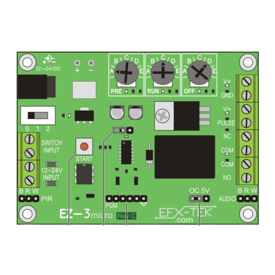
EZ-3micro Connections & Controls
A. Power input: 2.1mm barrel jack; 12 to 24 VDC
B. Power input pads: 12 to 24 VDC
C. Power switch (OFF / Configure / Run)
D. Switched power output
E. Start input: dry contact
F. Start input: 12 to 24 VDC
G. Start input: PIR
H
Start input: manual button
I.
PRE delay potentiometer
J. RUN time potentiometer
NOTE: While a programming header is provided for advanced users interested in hacking the
EZ-3u for their own purposes, EFX-TEK provides no support for hacking beyond a schematic for
the product. Schematic is available from www.efx-tek.com.
Power Input
The EZ-3u is powered from 12 to 24 volts DC. DC power may be connected to via the 2.1mm power jack (A)
or through the V+ and GND pads (B) located just above the power jack. When the power switch (C) is in
position 2 (Run) the input power is routed to the V+ and GND output terminal block (D); this can be useful for
providing power to the relay contacts or sharing power with other devices (e.g., audio controller).
2
K. OFF time potentiometer
L. High-current pulse output (valve, relay, etc.)
M. Open-collector/5V pulse output (audio player)
N. OC/5V configuration jumper
O Normally-closed relay output
P. Normally-open relay output
Q. Pot configuration jumper
R. Programming header (for hackers; see note)
EFX-TEK ● www.efx-tek.com ● [email protected]