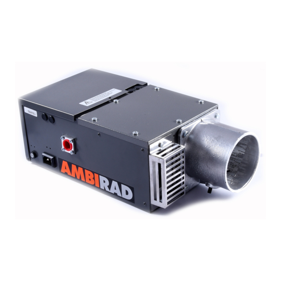
Ambirad AR35/50' SL Manual de instalação e manutenção - Página 16
Procurar online ou descarregar pdf Manual de instalação e manutenção para Aquecedor a gás Ambirad AR35/50' SL. Ambirad AR35/50' SL 20 páginas. Gas fired radiant tube heaters

- 1. Table of Contents
- 2. AR and ARE Series Gas Fired
- 3. Gas Connection
- 4. Standards
- 5. Assembly Instructions
- 6. Fitting Reflectors and End Caps
- 7. Burner/Fan/Damper Assembly
- 8. AR and ARE Series Double Linear
- 9. HB and DL Damper Settings
- 9. Installation – Suggested Methods
- 9. Of Heater Suspension
- 10. Flue Connection
- 11. Commissioning for Individually
- 12. Routine Service
- 13. Trouble Shooting Checklist
- 14. User Instructions for Ambi-Rad
15 Commissioning for individually
flued and unflued heaters
Inspect installation and ensure that it has
been carried out in accordance with these
instructions. Ensure that electrical and gas
supplies are isolated. The gas supply should
be purged and tested for soundness in
accordance with the BS 6891:1988, BGIM/16,
IGE Report 1M/2 and any other British
Standard and Codes of Practice. Open
isolating valve.
Remove the combustion chamber cover plate
or ducted air inlet connection by unscrewing
6 fixing screws. Take care not to damage the
sealing gasket. Inspect the burner and
electrode assemblies, ensuring these are
securely fixed and all electrical connections
securely made. Replace the cover plate or
ducted air inlet connection, ensuring that the
sealing gasket is correctly positioned and the
six screws are fully tightened. The heater will
not operate until this plate is refitted.
Open the control housing cover door by
unscrewing the securing screw. Ensure all
internal components are securely fixed and
all connections securely made.
Switch on the electrical supply to the heater
and observe the correct start up sequence
as follows:
The mains lamp (red) will illuminate. The ID
fan will start to run and the vacuum switch
checking relay (inside flame electronic
sequence control box) will pull in. Safe-start
checks are carried out automatically and a
purge period of approximately 9 seconds will
commence.
At the end of the purge period the ignition
sequence will commence. The spark ignition
will be energised producing a spark at the
ignition electrode. The gas shut off valve will
at the same time be energised. If ignition is
successful the flame is detected by the flame
sensing probe and the ignition spark will be
switched off. The 'burner on' (amber) lamp
indicates that the gas safety control valves
are energised.
16
If the ignition is unsuccessful the gas safety
control valve is closed and the spark ignition
de-energised after approximately 5 to 7
seconds. After an unsuccessful ignition
attempt the electronic sequence controller
will 'lock-out' . The 'power lamp' (red) only
will remain illuminated and the fan will
continue to run. To reset this 'lock-out'
condition, switch the power supply to the
heater, wait 15 seconds then restore it. If
repeated lock-out occurs investigate cause.
In the event of an electrical fault after
installation of the appliance preliminary
electrical systems checks should be carried
out (re-earth continuity polarity and
resistance to earth).
To shut down the heater, switch off the
power supply to the heater. Automatic
control of the heater or a series of heaters
may be achieved by incorporating
thermostats, time switches, frost thermostats,
manual over-ride switches etc., in the
electrical supply to the heater(s). It is essential
to allow a delay of 15 seconds after switching
off a heater before attempting to restart.
If at any time after completion of the start
up sequences, loss of flame should occur,
the electronic sequence controller will
attempt to re-ignite. If this is unsuccessful
lock-out will occur.
Set burner gas pressure as follows. Isolate gas
supply. Unplug mains input connector to
heater. Unscrew the fixing screw in the
hinged safety control housing lid and swing
away. Remove pressure test point screw
nearest the burner head and connect a 'U'
tube manometer to the pressure test nipple
located on the body of the gas valves.
Remove the slotted cover from the pressure
test regulator revealing the adjustable screw.
Replace mains input connector and start the
heater. Using a suitable screwdriver adjust
the pressure regulator. Switch off the heater
by pulling out the mains input connector.
Disconnect 'U' tube manometer and refit
screw in pressure test nipple. Replace cover
on pressure regulator. If heater is flued
check that there is adequate updraught
at the down-draught diverter eg. by means
of a smoking taper when heater is running.
Check the operation of the flame safe guard
equipment as follows. With the heater
running normally, switch off the gas supply
at the appliance isolating valve. Observe that
the 'burner on' lamp extinguishes within one
second. After a purge period of
approximately 9 seconds the heater should
attempt to re-light and if the gas isolating
valve has been left off, lock-out should
occur indicated by power light only being
illuminated and fan running.
Check the operation of the vacuum proving
switch as follows. With the heater running
normally pull out the three pin fan
connection plug, thus causing the fan to
slow down and stop. Within 3 seconds the
burner should shut off. Observe for at least
20 seconds that there is no attempt to
re-ignite, then replace the three pin plug
and observe that the heater proceeds to
ignite in the normal way.
Close the safety control housing lid which is
secured with the fixing screw.
Hand the 'User Instructions' to the user and
explain how to operate the heater.
Leave the 'Installation and Servicing
Instructions' at the user's meter or
preferably with the service/maintenance
engineer/manager for use on future service
calls.
Note It will be noted that heaters have a
tendency to bow when hot, this is normal
and quite acceptable.
