Flomatic CA501 Manual de operação e manutenção - Página 4
Procurar online ou descarregar pdf Manual de operação e manutenção para Unidade de controlo Flomatic CA501. Flomatic CA501 4 páginas. Automatic control valve
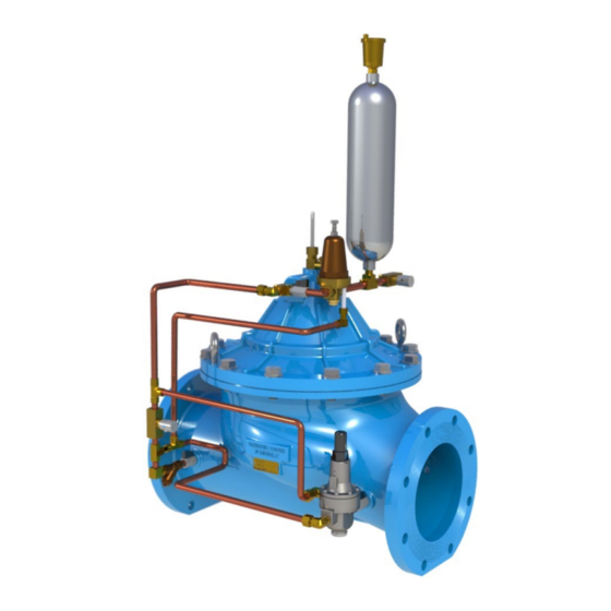
Automatic Control Valve
Operation & Maintenance Manual
Model C501/CA501 Surge Arrestor Valve
TROUBLE SHOOTING GUIDE:
CAUSE
1. Main valve is air bound.
2. Isolation valve at the inlet side of controls is closed.
3. Indicator stuffing box or sight glass is leaking (if
equipped).
4. Fouled orifice (or needle valve).
5. Fouled Y-strainer.
6. Damaged under pressure or over pressure pilot valve
seat.
7. Ruptured diaphragm in main valve.
8. Debris lodged under seat of main valve.
9. Worn seat seal and/or seat ring in main valve.
10. Incorrect adjustment of Under Pressure Pilot (set too
high).
11. Incorrect adjustment of Over Pressure Pilot (set too
low).
12. Leakage from one or more fittings in the controls.
13. Damaged o-ring stem seal.
PROBLEM: Valve is closed and will not open.
1. Incorrect adjustment of Over Pressure Pilot (set too
high).
2. Needle Valve open too far
3. Isolation valve at the outlet side of the controls is closed.
4. Fouled pilot valve(s)
5. Worn or eroded orifice (or needle valve seat).
15 Pruyn's Island Drive
Glens Falls, New York 12801
Phone: (800) 833-2040
PROBLEM: Valve opens and will not close.
CORRECTION
1. Open ¼" air bleeder located on top cover of valve to
release air.
2. Open isolation valve.
3. Tighten packing nut or replace packing seals.
4. Remove and clean orifice if required. Open needle valve
wide (counter clockwise) to flush seat. Return to original
setting after 4 or 5 seconds.
5. Disassemble, clean or replace screen.
6. Disassemble, clean and replace damaged parts.
7. Disassemble and replace diaphragm.
8. Disassemble and remove. Replace damaged parts.
9. Disassemble and replace damaged parts.
10. Turn Under Pressure Pilot adjusting screw counter-
clockwise slowly until valve resumes control and closes;
(refer to Section 6.2 for Under Pressure Pilot set point
adjustment).
11. Turn Over Pressure Pilot adjusting screw clockwise
slowly until valve resumes control and closes; (refer to
Section 6.1.a & 6.1.b for Over Pressure Pilot set point
adjustment).
12. Tighten or replace fitting.
13. Disassemble and replace o-ring.
1. Turn the Over Pressure Pilot adjusting screw counter-
clockwise slowly until the valve opens, then turn clockwise
untill the valve closes at the desired set point; (refer to
Section 6.1.a & 6.1.b for Over Pressure Pilot set point
adjustment).
2. Turn adjusting cap clockwise slowly until vavle opens
and then clockwise until valve re-closes
3. Open isolation valve.
4. Disassemble and clean, rebuild as necessary.
5. Replace orifice (or needle valve).
WWW.FLOMATIC.COM
High Quality Valves Built to Last...
MANUAL: C501 REV: 4