Flomec G Series Manual do Proprietário - Página 5
Procurar online ou descarregar pdf Manual do Proprietário para Instrumentos de medição Flomec G Series. Flomec G Series 16 páginas. Industrial and chemical models
Também para Flomec G Series: Manual do proprietário do produto (20 páginas), Manual do proprietário do produto (20 páginas)
5. Once the turbine flowmeter is taken
apart, inspect the turbine flowmeter
body for signs of wear or defects.
The body bore should be smooth
and show no evidence of wear.
NOTE: Do not install a new replace-
ment kit into a turbine flowmeter
body that shows significant signs
of wear.
6. Examine the rotor for broken and/
or bent blades.
7. Examine the supports for signs of
deterioration, such as wear marks
and/or burrs along the outer edge
of the support vanes.
8. When the rotor or the supports
show any sign of deterioration,
a new replacement kit should
be installed. Do not install a new
replacement kit into a defective
turbine flowmeter body.
Replacement Kits
A replacement kit is comprised of all
the internal component parts within
the turbine flowmeter. A replacement
kit consists of the following:
Parts Description
Rotor Assembly
Support Assembly*
Retaining Ring
*
The support assemblies come complete with bush-
ings and thrust balls, which are factory installed.
Proper selection of bearing material is critical when
ordering a new replacement kit.
FLOMEC
supports are identical in
®
design, thus eliminating assembly er-
ror. Each support incorporates a thrust
bearing, which allows for bidirectional
flow and prevents damage to the rotor
and/or supports in the event the tur-
bine flowmeter is installed backwards
with respect to the direction of flow.
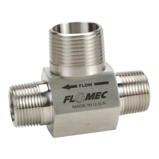
Notice that the direction of flow is
displayed on the body of the turbine
flowmeter. This is important when
921977-01C
installing the rotor and also denotes
the direction in which the turbine
flowmeter was calibrated.
NOTE: FLOMEC rotors are tapered on
1. Install a support on the inlet side
2. Place the rotor with the shaft in
3. Once the support is in place, install
4. Blow into the turbine flowmeter to
Quantity
Installation of the replacement kit is
1
complete and the turbine flowmeter
2
can be reinstalled into the process line.
2
5. Install the magnetic pickup. HAND
NOTE: Be sure to use the proper
6. Enter the new K-factor supplied
NOTE: All internal replacement kits
one end (except ½" and ¾"). The
tapered end should be installed
on the inlet side. See Figure 1.
The ½" and ¾" rotors are marked
with a point on the hub and should
be installed with the marked side
of the rotor hub on the inlet side.
(where the flow starts), placing a
vane between the notches in the
turbine flowmeter body. Install a
retaining ring – this will keep the
support in place.
the support that has not been in-
stalled. Hold the turbine flowmeter
body with the open end down and
slide the rotor and support into the
turbine flowmeter body. Make sure
the vane is placed between the
notches.
the retaining ring.
ensure the rotor spins freely.
TIGHTEN ONLY.
magnetic pickup, cable and con-
nector for the application.
with the replacement kit into the
electronic readout device. (Refer
to the calibration report.)
are factory calibrated and are sup-
plied with a five point calibration
certificate.
5