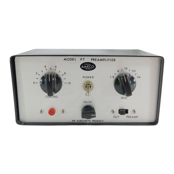
Ameco PT Manual de instruções - Página 6
Procurar online ou descarregar pdf Manual de instruções para Amplificador Ameco PT. Ameco PT 9 páginas. Preamp tube type

t.
ALIGNMENT
PROCEDURE
The
preamplifjer
in
the
PT
has no
adjustments.
All
tuning
is
done
by
the variable
con-
denser.
Cl
'is a
reactance
cancelling capacitor which'is
used
to
reduce
the
SWR
to
less
than
l.l:l
The
adjustment procedure
is
as follows:
l.
Connect
a transmitter to a
standing
wave
bridge.
2.
Connect
the
PT
Pl to
the
bridge.
3.
Connect
a
good 50
ohm dummy
load
(such
as.
Bird, Sierra,
etc.) to
the
PT
Jl.
4.
Short
PT PZ
during
this
whole
test,
the
power
MUST
be on
the
PT.
5.
Tune
up
the transmitter
on
52
MHz
if
ava'ilable, otherwise on the
h'ighest frequency
on
the
transmitter.
Use 35
watts
minimum.
6.
Switch
to
read
reflected
power.
7.
Adjust
C1
for
a
mjnimum
reading.
Do
not
disturb Cl
except
in
the
complete procedure
above.
REPLACEMENT
OF THE
FUSE/RES|STOR
To replace
fuse/resistor
R10, use
only
Allen
Bradley
or
0hmite carbon composit'ion,
l/1O-watt
size.
Do
not
use
l/4-watt or
deposited carbon
resistors
as they
will
not
break
quickly
enough.
Unsolder
the
remains
of
the
broken
res'istor
from
the lug
and
the spring
wire.
Solder
one end
of
the
rep'lacement
resistor to
the terminal
lug.
Hook
the other
end
oVei ttre spring
wire
and pu11
the lead
until
the spring
is
-dEiieeted about
1/16
inch.
hlh'ile
holding
this
position,
solder the resistop lead
to
the spring
wire.
Before unsoldering diodes
CR2
and CR3, check
with
an ohmmeter. Diodes
are
good
if
the
reading
is
.l00
ohms
or
less
jn
e'ither
polarity.
If
the
reading
is
high
in
one
pol
ari
ty,
repl ace
the
two d'iodes
wi
th
type
'l
N281 on1y.
PARTS LIST
Most
components
used
in
th'is
unit
are available as over the counter items
at
any radio
parts
supply
store.
Listed
below,
are
specia'l items
that
are obtainable
from
AEROTR0N
on1y.
ITEM
DESCRIPTION
PART
NO.
R10
CR2
CR3
K1
LI
L2
L3
L4
S2
TI
T2
100 ohm, t70%, 7/10
watt,
comp.
Diode,
I N28l
D'iode
,
I
N28l
Re"lay, 4PDT,
I
l0
VDC
coi
I
Cojl, l.B-4
MHz
Coil,
4-.l0
MHz
Co'il, l0-23
MHz
Coi1,
23-54 lt1z
Swjtch,
rotary,
2
po1e,
4 posjtjon
Transformgr, Toroid
Transformer,
Power
47a5
loo3
oor
4804 0000
006
4804 0000
006
4507 0000
002
lB20 l615
021
I
820
1
615
022
tB20
t6t5
023
1805 I 615
024
5ll0
0000
017
5649
I
601
A25
56.1
0
0000
0t
9
2.
3.
4.
