Ekinex EK-ET2-TP Manual de início rápido - Página 3
Procurar online ou descarregar pdf Manual de início rápido para Controlador Ekinex EK-ET2-TP. Ekinex EK-ET2-TP 8 páginas. Room temperature controller with humidity and co2 equivalent regulator

two screws (c);
• snap the plate (a);
• snap the rocker (b) to complete the installation.
a
b
d
c
e
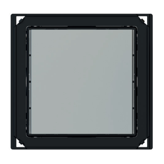
a) 1-fold plate (square, with 60 x 60 mm window)
b) Rocker
c) Screws (for device)
d) Device
e) Screws (for metallic support)
f) Metallic support
g) Plastic adapter
h) Rectangular frame (not for NF version)
i) Flush-mounting box (not delivered by ekinex
Mounting position
For optimum regulation the device has to be preferably
installed on an internal wall at the height of 1.5 m and at
least 0.3 m far from doors. The device cannot be installed
close to heat sources such as radiators or domestic ap-
pliances or in positions subject to direct sunlight. If neces-
sary, for the regulation may be used a weighted average
between two values selected among the following ones:
value measured by the internal sensor, value measured
by a temperature sensor connected to a device input, va-
lue received via bus by another KNX device (e.g. from
ekinex pushbuttons).
Switching, display and measuring elements
The device is equipped with a programming LED, 8 di-
splaying LEDs with lightguides for feedback status and
3 sensors.
Switching elements
• Pushbutton (13) for switching between the normal and
programming operating mode.
Display elements
• White / red LED (4) for indication of the heating mode
functionality active / heating ON;
• White / blue LED (5) for indication of the cooling mode
functionality active / cooling ON;
• Blue LED (6) for indication of the dehumidification fun-
ctionality ON;
• Green LED (7) for indication of the humidification fun-
ctionality ON;
f
g
h
i
)
®
1,50 m
• Red LED (8) for indication that the measured CO
valent exceeds threshold 3;
• Blue LED (9) for indication that the measured CO
valent lies between threshold 2 and 3;
• Blue LED (10) for indication that the measured CO
equivalent lies between threshold 1 and 2;
• Blue LED (11) for indication that the measured CO
equivalent lies below threshold 1;
• Red LED (12) for indication of the active operating
mode (on = programming, off = normal operation).
For measuring purposes the device is provided with:
• a temperature sensor (not visible, positioned behind
the passage 15);
• a relative humidity sensor (14);
• a CO
equivalent air quality sensor (16).
2
1
2
4
5
6
7
13
1) Terminal block for KNX bus line
2) Product label
3) Adapter
4) White (heating mode active) or red (heating ON) LED
5) White (cooling mode active) or blue (cooling ON) LED
6) Blue LED (dehumidification ON)
7) Green LED (humidification ON)
8) Red LED (CO
equivalent concentration > threshold 3)
2
9) Blue LED (CO
eq. concentration between threshold 2 and 3)
2
10) Blue LED (CO
eq. concentration between threshold 1 and 2)
2
11) Blue LED (CO
equivalent concentration < threshold 1)
2
12) Programming LED
13) Programming pushbutton
14) Relative humidity sensor
15) Temperature sensor
16) CO
equivalent sensor
2
i
Note. Programming pushbutton and LED are ac-
cessible from the front side of the device. The de-
vice addressing may be easily carried out after the
assembly of the frame, removing the rockers. Once
the addressing has been done, the device configu-
ration can be later downloaded without pressing the
programming pushbutton.
3
equi-
2
equi-
2
12
8
9
10
11
15
16
14
2
2
