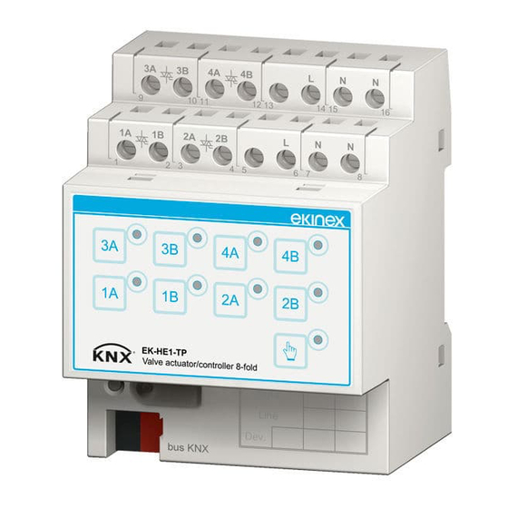
Ekinex EK-HE1-TP Manual - Página 3
Procurar online ou descarregar pdf Manual para Controlador Ekinex EK-HE1-TP. Ekinex EK-HE1-TP 5 páginas. Actuator / controller for electrothermal actuators

1
3
i
Note. When mounting the device in boards and ca-
binets it shall be provided the necessary ventilation
so that the temperature can be kept within the ope-
rating range of the device.
• rotate the device towards the rail (3);
• push the locking device upward until it stops (4).
Before removing the device, be sure that power supply
and controlled loads have been disconnected and the bus
terminal has been extracted from its slot. Use a screwdri-
ver to slide down the locking device and remove the de-
vice from the rail.
Connection of the KNX bus line
The connection of the KNX bus line is made with the ter-
minal block included in delivery and inserted into the slot
at the bottom of the housing.
Characteristics of the KNX terminal block
• spring clamping of conductors
• 4 seats for conductors for each polarity
• terminal suitable for KNX bus cable with single-wire
conductors and diameter between 0.6 and 0.8 mm
• recommended wire stripping approx. 5 mm
• color codification: red = + (positive) bus conductor,
black = – (negative) bus conductor
3A
3B
4A
9
10
11
1A
1B
2A
1
2
3
bus KNX
+
KNX
Bus
-
!
Warning! In order to supply the KNX bus lines use
only KNX bus power supplies (e.g. ekinex EK-AB1-
TP or EK-AG1-TP). The use of other power supplies
can compromise the communication and damage
the devices connected to the bus.
2
4
4B
L
N
N
12
13
14
15
16
2B
L
N
N
4
5
6
7
8
Area
Line
Dev.
Connection of the power supply
The connection of the 230 Vac or 24 Vac power supply is
made with the screw terminals (L, N) located at the top
front of the device.
Characteristics of the terminals
• screw clamping of conductors
• maximum cross section of conductor 2,5 mm²
• recommended wire stripping approx. 6 mm
• torque max 0,5 Nm
Warning! The electrical connection of the device
!
can be carried out only by qualified personnel. The
incorrect installation may result in electric shock or
fire. Before making the electrical connections, make
sure the power supply has been turned off.
Connection of the outputs
The connection of the outputs is made with the screw ter-
minals located at the top front of the device.
Characteristics of the terminals
• screw clamping of conductors
• maximum cross section of conductor 2.5 mm² (single-
wire) or 1.5 mm² (multi-wire)
• recommended wire stripping approx. 6 mm
• torque max 0.8 Nm
To reduce the total starting current, in case of simulta-
neous activation of two or more output channels, it is pre-
ferable to enable the delayed start function during confi-
guration via the ETS; in this case, each output channel
is activated with a delay time after the previous channel.
The delay is adjustable in the range 5 ... 40 s and is equal
for all channels.
!
Warming! The number of electrothermal actuators
that can be connected in parallel to each output is
limited by the rated current and the starting current
of the device. Carefully check the information on
the technical documentation of the manufacturer of
actuators.
Connection in 4-pipe systems
230 Vac or
24 Vac
1 2
Valve actuator
(heating)
1 2
3
L
N
3A
3B
4A
4B
L
N
N
9
10
11
12
13
14
15
16
1A
1B
2A
2B
L
N
N
1
2
3
4
5
6
7
8
Area
Line
Dev.
bus KNX
Valve actuator
(cooling)
