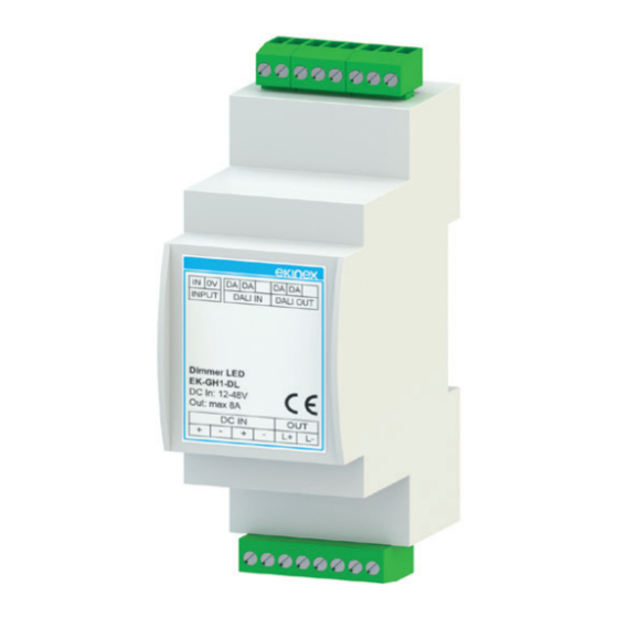
Ekinex EK-GH1-DL Manual de início rápido
Procurar online ou descarregar pdf Manual de início rápido para Regulador de fluxo luminoso Ekinex EK-GH1-DL. Ekinex EK-GH1-DL 6 páginas. Dali 1-channel dimmer

DALI 1-channel dimmer
Code: EK-GH1-DL
S
DALI bus dimmer with 12/24/48 Vdc power supply, it pro-
vides LED sources brightness control function. Dimming
can can be managed by using different types of comman-
ds: KNX buttons or other local control devices.
Description
The ekinex DALI 1-channel dimmer EK-GH1-DL allows
brightness control of dimmable LED sources by means of
several kinds of button. It can be connected by means of
KNX (TP) pushbutton connected to a DALI / KNX Gate-
way or via another command device, directly connected
to the dedicated input, selectable from a normally open
button, 0-10V analog input, 1-10V analog input and 10 kΩ
potentiometer. The device has an integrated DALI bus
communication modules voltage and requires a 12, 24 o
48 Vdc input power supply.
Functional characteristics
• Constant voltage dimmer
• DALI bus command
• Number of channels: 1
• Local command: N.O. pushbutton / analog input 0-10V
/ 1-10V / 10 kΩ Potentiometer
• Brightness adjustment for LED loads
• Voltage output for R-L-C loads
• Typical efficiency > 95%
• Brightness adjustment up to full off (Dim to Dark)
• Minimum brightness level: 0.1% (1% in push)
• D-PWM Modulation
• Adjusting D-PWM frequency: 300 / 600 / 1200 Hz
• Adjusting output curve: Linear / Quadratic / Exponential
• Soft start and soft stop
Technical data
Inputs
• Input (constant voltage): 12 / 24 / 48 Vdc
• Supply voltage: min: 10,8 Vdc .. max: 52,8 Vdc
• Power absorbed while awaiting command: <500 mW
Datasheet STEKGH1DL_EN
1
Outputs
• Output voltage = input voltage
• Output current: max 8 A peak, max 7,5 A @55°C, max
6,5 A @60°C
• Nominal power @12V: 78 W (@6,5A) – 90W (@7,5A)
• Nominal power @24V: 156 W (@6,5A) – 180W (@7,5A)
• Nominal power @48V: 312 W (@6,5A) – 360W (@7,5A)
• Thermal shutdown: 150 °C
• Command supply current: 0,5mA (for 1-10V)
• Command required current (max): 0,1mA (for 0-10V)
i
Note: the values for output current have to be inten-
ded as maximum values, depending on the ventila-
tion conditions.
Dimming
• Dimming frequency D-PWM: 300Hz – 600Hz – 1200Hz
• Resolution D-PWM: 16 bit
• Dimming range D-PWM: 0,1-100%
Environmental conditions and other characteristics
• Operating temperature: -40 ° C ... + 60 ° C
• Storage temperature: - 40 ° C ... + 60 ° C
• Transport temperature: - 40 ° C ... + 60 ° C
• Relative humidity: 93% non-condensing
• Protection degree IP10 (device installed)
• Command & bus wiring: 1.5 mm
ded – 30-14 AWG
• Power & LEDs wiring: 2.5mm
– 30-12 AWG
• Command & bus stripping: 6 mm
• Power and LEDs stripping: 7.5 mm
• Housing in plastic material
• Safety class II
• Weight 67 g
• Modular device 2 MU (1 MU = 18 mm)
• Dimensions 91 x 36 x 62 mm (LxHxP)
Protections
The device is provided with the following protections:
• OTP Over temperature protection
• OVP Over voltage protection
• UVP Under voltage protection
• RVP Reverse polarity protection
• IFP Input fuse protection
• SCP Short circuit protection
• CLP Current limit protection
1) Thermal Protection on the output channel in case of high temperature. The thermal
intervention is detected by transistor (>150°C).
2) Control logic protection only
Control, signaling and connection elements
The device is equipped with a screw terminal for connec-
ting the 12 / 24 / 48 Vdc input power supply and the output
loads (1), a screw terminal for connecting the local com-
mands and the DALI line (2) and one signaling LED (3).
solid – 1 mm
stran-
2
2
solid – 1.5 mm
stranded
2
2
1
2
2
2
2
