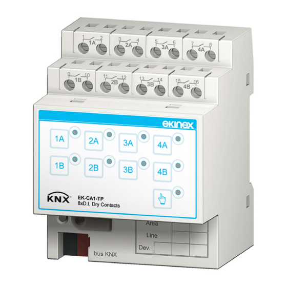
Ekinex KNX EK-CA1-TP Manual de início rápido - Página 3
Procurar online ou descarregar pdf Manual de início rápido para Interruptor Ekinex KNX EK-CA1-TP. Ekinex KNX EK-CA1-TP 4 páginas. 8-fold analog/binary input

1A
1
2
9
1B
10
1A
1B
+
KNX
bus
-
a
Connection of the KNX bus network
Connection of the inputs
The connection of the inputs (fig. b, c, d) is made with the
screw terminals located at the top.
!
Warning! The electrical connection of the device
can be carried out only by qualified personnel. The
incorrect installation may result in electric shock or
fire. Before making the electrical connections, make
ca1 4can
sure the power supply has been turned off.
1 1A
2
3
4
5
2A
3A
Connection for 8 independent inputs for potential-free contacts, e.g., for tra-
b
ditional (not bus) switches or pushbuttons dedicated to the on/off switching
of loads
L
1 1A
2
3 2A
9 1B
10
11 2B
Connection as 4 pairs of inputs (coupled inputs for dimming of lighting devi-
c
ces or controlling drives for shading devices, such as shutters, blinds, cur-
ca1 4can
tains, etc.
Collegamento come 4 ingressi configurabili singolarmente per sonde di tem-
d
peratura passive (NTC 10 kΩ a 25 °C).
2A
3A
4A
3
4
5
6
7
8
2B
13
3B
15
4B
16
11
12
14
2A
3A
4A
2B
3B
4B
EK-CA1-TP
8xD.I. Dry Contacts
bus KNX
6
7 4A
8
9 1B
10
11 2B
12
13 3B
4
5 3A
6
12
13 3B
14
Characteristics of the terminals
• screw clamping of conductors
• maximum cross section of conductor 2.5 mm² (single-
wire) or 1.5 mm² (multi-wire)
• recommended wire stripping approx. 6 mm
• torque max 0.8 Nm
!
Configuration and commissioning
Configuration and commissioning of the device require
the use of the ETS
V4 or later releases. These activities must be carried out
according to the design of the building automation system
done by a qualified planner.
Product
code
EK-CA1-TP
Configuration
For the configuration of the device parameters the corre-
sponding application program or the whole ekinex
duct database must be loaded in the ETS program. For
detailed information on configuration options, refer to the
application manual of the device available on the website
www.ekinex.com
i
14
15 4B
16
Commissioning
For commissioning the device the following activities are
required:
• make the electrical connections as described above;
• turn on the bus power supply;
• switch the device operation to the programming mode
7
8
4A
by pressing the programming pushbutton located on
the front side of the housing. In this mode of operation,
15 4B
16
the programming LED is turned on;
• download into the device the physical address and the
configuration with the ETS
At the end of the download the operation of the device
automatically returns to normal mode; in this mode the
programming LED is turned off. Now the bus device is
programmed and ready for use.
3
Warning! If configured as analog input, the
connection of a NTC temperature sensor with a
characteristic resistance value of 10 kΩ at 25°C,
β = 3435 is allowed only.
(Engineering Tool Software) program
®
Application
Communica-
program (## =
tion objects
release)
(max nr.)
APEKCA1TP##.knxprod
430
Note. The configuration and commissioning of KNX
devices require specialized skills. To acquire these
skills, you should attend the workshops at KNX cer-
tified training centers.
program.
®
Group
adressses
(max nr.)
254
pro-
®
