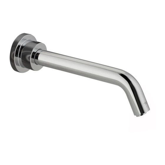
American Standard SERIN T064.342 Manual de instruções de instalação - Página 11
Procurar online ou descarregar pdf Manual de instruções de instalação para Cozinha & amp; Acessórios de casa de banho American Standard SERIN T064.342. American Standard SERIN T064.342 12 páginas. Wall mount electronic proximity lavatory faucet

D
HOW TO CLEAN AND REMOVE
THE AERATOR OR SPRAY; Fig. 4
1. Remove AERATOR or SPRAY HOUSING (7) with
KEY supplied with faucet.
2. Remove AERATOR or SPRAY (8) from HOUSING (7).
3. Clean the AERATOR or SPRAY SCREEN (9).
4. Reassemble and install into spout end. Be sure the
black seal washer is in place.
HOW TO CLEAN FLOW
E
REGULATOR; Fig. 5
1. Remove SUPPLY HOSE (10) from SPOUT ELBOW
ASSEMBLY (11). Pull out FLOW REGULATOR (12)
from SPOUT ELBOW ASSEMBLY (11).
2. Clean FLOW REGULATOR (12). Replace FLOW
REGULATOR (12) and reassemble SUPPLY HOSE (10)
to SPOUT ELBOW ASSEMBLY (11).
GENERAL CLEANING; Fig. 5
F
1. Only use a damp, soft cloth to clean the spout and
the sensor.
2. For tougher dirt, use a soft cloth with diluted dish
washing detergent. Wipe the area using a wet cloth
and dry using a soft cloth.
CAUTION
Do not scratch the sensor when cleaning.
Avoid using any abrasives or harsh detergents
or chemicals.
FAQ'S
Q: How will I know if the battery needs to be replaced?
A: Valve will not open and sensor will continuously blink 2 times interrupted by a pause for up to 7 days.
Q: Why has the flow rate of the faucet reduced significantly?
A: The filter assembly, flow regulator or areator/spray may be clogged. Check and clean. Refer to Start-up/Mainenance,
sections C, D and E.
Q: Why doesn't the water flow out of faucet when I'm within the sensor detection zone?
A: Battery may need replacement. Check. If sensor continuously blinks 2 times interrupted by pause, replace battery
or call (855) 752-9259.
Q: What is the normal operating pressure range?
A: Faucet will operate with supply pressures ranging from 20-80 psi.
Fig. 4
7
Fig. 5
RINSE TO CLEAN FLOW
REGULATOR
12
10
11
Fig. 6
10
9
8
KEY
M 9 6 5 6 13
7
