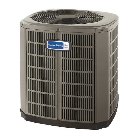
American Standart 4A6H4 Manual do instalador - Página 5
Procurar online ou descarregar pdf Manual do instalador para Bomba de calor American Standart 4A6H4. American Standart 4A6H4 8 páginas.

If a defrost control problem is suspected, refer to the service in-
formation in control box.
G. COMPrESSOr STArT-UP
After all electrical wiring is complete, SET THERMOSTAT SYS-
TEM SWITCH IN THE OFF POSITION SO COMPRESSOR WILL
NOT RUN, and apply power by closing the system main disconnect
switch. This will activate compressor sump heat (where used). Do
not change the Thermostat System Switch until power has been
applied for one (1) hour. Following this procedure will prevent
potential compressor overload trip at initial start-up.
h. OPErATIONAL AND ChECkOUT PrOCEDUrES
Final phases of this installation are the unit Operational and
Checkout Procedures which are found in this instruction on
page 8. To obtain proper performance, all units must be operated
and charge adjustments made in accordance with procedures
found in the Service Facts.
IMPOrTANT:
Perform a final unit inspection to be sure that factory tubing has
not shifted during shipment. Adjust tubing if necessary so tubes
do not rub against each other when the unit runs. Also be sure
that wiring connections are tight and wire routing is secure.
I. ELECTrIC hEATErS
Electric heaters, if used, are to be installed in the air handling
device according to the instructions accompanying the air han-
dler and the heaters.
J. OUTDOOr ThErMOSTAT
An outdoor thermostat TAYSTAT250B may be field installed.
For data, see wiring diagram attached to unit and instruction
sheet packaged with outdoor thermostat.
Notes:
1. Be sure power supply agrees with equipment nameplate.
2. Power wiring and grounding of equipment must comply with local codes.
3. Low voltage wiring to be No. 18 AWG minimum conductor.
4. ODT-B must be set lower than ODT-A.
5. If outdoor thermostats (ODT) are not used, connect W1 to W2 and W3.
6. N/A to programmable thermostat.
Pub. No. 11-BC08D1-7
TyPIcAL fIELD Hook-UP DIAGRAMS
INSTALLER'S GUIDE
k. SEACOAST SALT ShIELD
If installed within one mile of salt water, including seacoasts and
inland waterways, models without factory supplied Seacoast Salt
Shields require the addition of BAYSEAC001 (Seacoast Kit) at
installation time. Please refer to Application Guide SS-APB007
-EN: Seacoast Applications and Seacoast Corrosion Protection
Bulletin UN-SVB11A-EN.
TRoUbLESHooTING cHART — wHAT To cHEck
SYSTEM FAULTS
REFRIGERANT CIRCUIT
C
Head Pressure Too High
H
C
Head Pressure Too Low
H
C
Suction Pressure Too High
H
C
Suction Pressure Too Low
H
C
Liquid Refrig. Floodback (TXV)
H
C
Liquid Refrig. Floodback
(Cap. Tube)
H
C
I.D. Coil Frosting
H
C
Compressor Runs
Inadequate or No Cooling/Htg
H
ELECTRICAL
C
P
P
Compressor & O.D. Fan
Won't Start
H
P
P
C
P
S
P
S
S
Compressor Will Not Start
But O.D. Fan Runs
H
P
S
P
S
S
C
P
P
O.D. Fan Won't Start
H
P
P
C
P
S
S
Compressor Hums But Won't Start
H
P
S
S
C
P
S
P
S
S
Compressor Cycles on IOL
H
P
S
P
S
S
C
P
P
I.D. Blower Won't Start
H
P
P
DEFROST
C
Unit Won't Initiate Defrost
H
C
Defrost Terminates on Time
H
C
Unit Icing Up
H
C - Cooling
H - Heating
P - Primary Causes
LEGEND
FACTORY WIRING
FIELD WIRING
P
P
S
P
S
P
P
S
P
S
P
S
S
S
P
S
S
S
P
P
S
S
S
P
S
P
P
S
S
S
P
P
P
S
S
S
P
P
S
S
S
P
S
S
S
P
S
S
S
P
S
P
S
S
P
S
P
S
P
P
S
P
S
P
P
S
P
S
P
S
S
S
P
S
P
S
P
S
P
P
S
S
S
S
S
P
S
P
P
S
S
S
P
S
P
S
S
S
P
S
S
P
P
S
S
S
*
S - Secondary Causes
- 3 Phase Only
S
S
S
S
S
P
S
S
P
P
P
P
S
S
S
P
P
S
S
S
S
S
S
S
S
S
S
P
P
P
P
P
P
PAGE 5
