American Time SiteSync IQ Manual de instalação e operação - Página 6

Procurar online ou descarregar pdf Manual de instalação e operação para Transmissor American Time SiteSync IQ. American Time SiteSync IQ 13 páginas. Wireless system controller with standard gps & magnetic mount tx antenna
Também para American Time SiteSync IQ: Manual de instalação de início rápido (2 páginas), Manual de instalação e operação (2 páginas), Manual de instalação e operação (7 páginas), Manual de instalação e operação (6 páginas), Manual de instalação de início rápido (2 páginas), Manual de instalação de início rápido (2 páginas), Manual de instalação de início rápido (2 páginas), Manual de instalação de início rápido (2 páginas), Manual de instalação de início rápido (2 páginas), Manual de instalação de início rápido (2 páginas), Manual de início rápido (2 páginas), Manual de início rápido (2 páginas), Manual de início rápido (2 páginas)
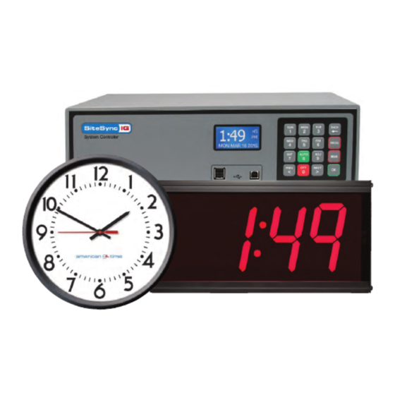
American Time SiteSync IQ Manual de instalação e operação

Operation

Side & Front View
2
1
4
1.
Power Switch
2.
Power LED
3.
3 Position Relay Switches
4.
RCA Jack
5.
Tone Card
6.
Bell Relay 1 Surge Switch
7.
Bell Relay 2 Surge Switch
8.
Bell Relay 3 Surge Switch
9.
Bell Relay 4 Surge Switch
10. Power Input Fuse
11. Hot
12. Neutral
13. Ground
14. Relay Connections
15. Relay Output Fuses
A power switch (#1) is located on the left side of the SiteSync IQ Wireless Controller. When power is connected and the power
switch is in the on position the power LED (#2) located in the top right corner of the front panel will light red.
WARNING
The power switch only removes power to the internal circuitry of the SiteSync IQ Wireless Controller. If performing
maintenance within the wiring panel located at the bottom of the SiteSync IQ Wireless Controller, power should be
removed prior to service.
Bell Relays
The SiteSync IQ Wireless Controller can be thought of as an extension to the SiteSync IQ System Controller wired relays. When
the SiteSync IQ System Controller activates its on-board wired relays, it also sends out a message to activate the SiteSync
IQ Wireless Controller relays. Each wired relay on the System Controller corresponds to the same wired relay on the Wireless
Controller: i.e. Bell one on the system controller corresponds to bell one on the wireless controller; Bell two corresponds to bell
two, and so on.
Each Wireless Controller bell relay comes equipped with a three position switch (#3). These switches allow the user to manually
operate each circuit, turn them off or allow automatic control from the SiteSync IQ System Controller via wireless signals.
The bell relays on the SiteSync IQ Wireless Controller can be manually activated by moving the corresponding switch to the top
(On or Test) position. A red LED will light indicating that the relay is currently active.
To disable a relay simply place the corresponding switch in the center position. The LEDs above and below the relay switch will
turn off when the corresponding switch is in the OFF position.
Automatic bell relay operation is achieved by placing the corresponding switch in the down (Auto) position. In this position the
SiteSync IQ System Controller has complete control of the bell relay. A yellow LED will light indicating the relay is ready for a
message from the System Controller. A red LED will light indicating the relay is active.
6
5
3
8
7
6
9
16. NC Surge Switch
Clock B
17. NO Surge Switch
10
Clock B
18. NC Surge Switch
Clock A
19. NO Surge Switch
Clock A
SiteSync IQ Wireless Controller
Front View - Open
18
19
13
11
12
Installation Manual
17
16
15
14
© American Time