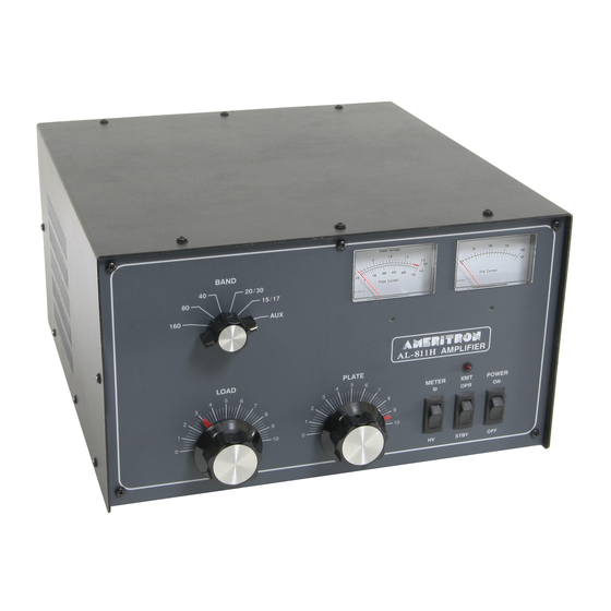
AMERITRON AL-811HY Manual de instruções de desembalagem
Procurar online ou descarregar pdf Manual de instruções de desembalagem para Amplificador AMERITRON AL-811HY. AMERITRON AL-811HY 11 páginas.
Também para AMERITRON AL-811HY: Manual (13 páginas)

PLEASE READ THIS MANUAL BEFORE ATTEMPTING TO OPERATE EQUIPMENT!!
1. Carefully lift the amplifier by the bottom cabinet edge out of the shipping carton. Place the
amplifier on a firm, level surface and carefully inspect it for shipping damage. Contact the
shipper immediately if any damage exists. Save the carton and packing material for possible
shipping in the future.
2. Remove the twelve screws holding the cover on with a number 2 phillips screwdriver.
Carefully lift the cover off the amplifier. Save the screws to rescuer the cover. Note that the
AL811H is shipped with the fuses and fuse caps inside the amplifier.
3. Locate the fuse pack with the two 12 ampere fuses and fuse caps. If additional screws are
needed, they will be in the fuse pack also. NOTE: Fuses supplied are for 120/110/100V
operation (Models AL-811H/HY). If you are rewiring the AL-811H for 240/230/220V
operation, you must use 8 ampere fuses. The AL-811HX export model is pre-wired for
240V operation and is supplied with 8 ampere fuses.
4. Remove the foam packing material (around the tubes) that secures the 811A tubes during
transit. Carefully unwrap the tubes. Do not dislodge or break the shaft that is connected to
the rear input bandswitch wafer.
5. To install the tubes in the sockets, be sure the large diameter pins line up with the two large
diameter holes in each socket. Do NOT rock or twist the tubes excessively during the
installation. If the tubes are already installed, check them for proper seating. If necessary,
press the tubes down into their sockets with gentle force. Do not rock or twist the tubes
excessively. Also, check that the anode caps are secure and that they did not come loose
during the unwrapping process.
6. The white ceramic anode connector will have to be removed from the top metal cap of each
tube if it ever becomes necessary to remove the tubes from the amplifier. This can be a
difficult procedure because the high clamping force of the internal springs in the anode
connector may hold it to the cap very tightly. The tube will break if direct upward or rocking
pressure is applied in an attempt to remove the connector. The safest way to remove the
ceramic connector is to lift the tube out of its socket. A twisting or spinning pulling motion
can then be applied while holding the ceramic connector firmly until the tube and connector
are separated. Repeat the procedure with each tube.
7. Install the cover with the vent holes to the left (near the tubes) by installing the back screws
first. Install all the screws loosely and tighten them only after all the screws are in place.
8. Install the fuses and fuse caps on the back of the unit. Read the manual to become familiar
with the operation of the AL-811H amplifier.
From The N3UJJ.COM Document Library
From The N3UJJ.COM Document Library
UNPACKING INSTRUCTIONS
