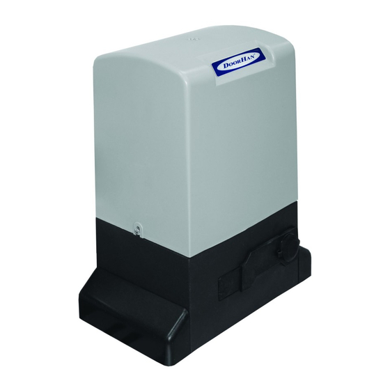
DoorHan SLIDING-1300 Manual de instalação e funcionamento - Página 9
Procurar online ou descarregar pdf Manual de instalação e funcionamento para Abertura de portões DoorHan SLIDING-1300. DoorHan SLIDING-1300 16 páginas. Drive
Também para DoorHan SLIDING-1300: Manual de instalação e funcionamento (12 páginas), Manual de instalação e operação (12 páginas)

Control unit LeDs
Indicator
pWR
A (red)
B (green)
ST
RED
ph1
ph2
STOp
Sw1
Sw2
States of light diodes when the door is in middle position and does not move are shown in bold.
electrical connectors
1. ~220 (n, L, Pe) — connector on the control unit used for connection to supply voltage unit.
pE — earth connection
N — power supply (neutral)
L — power supply (phase)
2. MotoR (n, L1, L2) — connector on the control unit used for connection to electric motor unit. Make sure that the motor is
connected as shown in the electric diagram.
3. LAMP — connector used for connection of signal lamp 230 V max 40 W. It works by any move of the door leaf. The lamp
blinking period is 0.5–1 sec.
Low voltage contacts used for accessories
1. stARt — Full open command (no)
Closing of contacts of the device connected to this terminal will cause actuation of control unit for full open and/or close of the
door (the exact logic depends on position of Dip1 switch).
Dip1 — off. The commands are produced in the Open-Stop-Close-Stop cycle mode.
Dip1 — on. The commands are produced in the Open-Close-Stop-Open mode (there will be no stop at the moment of move).
Control unit will take the Start command in ~1–2 sec after its previous receipt on the input.
If you need to connect several devices, connect the normally opened (NO) contacts of these devices parallel.
2. Ped — Pedestrian passage command (no)
Dip2 — off. The ped command allows you to open the door by approximately 1 m. After the repeated command the door will
close. If the ped command is followed by the Start command, control unit will produce the command for full close of the door.
The ped command when Dip2 is off will open the closed door by 1 m and will close the opened door.
Dip2 — on. Separate control of the operator, that is the Start command will open the door and the ped command will close the door.
To connect several devices you should connect the normally opened (NO) contacts of these devices parallel.
3. sW oP / sW CL — signals from the limit switches of door leaf end positions.
Actuation (breaking of contacts) of limit switch SW Op/ SW CL means that the door leaf in end open/closed position and must
not move in this direction any more.
4. Photo Cl — contacts for connection of close safety devices (NC). Actuation of these devices will cause immediate reverse of the
door leaf until full opening. Actuation of the devices connected to these terminals does not effect operation during opening of the door.
If the sensors connected to these terminals actuated when the door is open, the door will not close.
To connect several devices with NC contacts, connect them in series.
note! If no devices are connected to these terminals, place a jumper between the contact terminals Ph CL and — (see the
electric diagram).
Function
Motor supply voltage
Add remote control code
Emergency conditions
START command
pED command
Close photocells
Open photocells
STOp command
Close limit switch
Open limit switch
electrIcal cOnnectIOns
Glows
Yes
Yes
Yes
Yes
Yes
not actuated
not actuated
Yes
Closed
Closed
Does not glow
No
no
no
No
No
Actuated
Actuated
No
Actuated
Actuated
9
