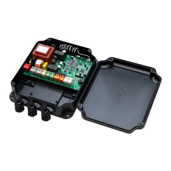
DoorHan PCB-SW Manual de instruções de programação - Página 11
Procurar online ou descarregar pdf Manual de instruções de programação para Painel de controlo DoorHan PCB-SW. DoorHan PCB-SW 20 páginas. Control board
Também para DoorHan PCB-SW: Manual de instruções de programação (20 páginas)

To install several devices connect their N.O. contacts in parallel.
13-15. OP FOTO — opening safety devices contact (NC): the purpose of this contact is to prevent people, animals and foreign
items from jamming during gate opening. If the opening safety devices are engaged when the drive is operating then they stop
the gate movement.
If the opening safety devices are engaged when the gate is closed then they prevent any gate movement.
WARNING!
If no devices are connected to these terminals install a jumper between the contacts 13-15.
14-15. CL FOTO — closing safety devices contact (NC): the purpose of this contact is to prevent people, animals and foreign
items from jamming during gate closing. If the closing safety devices are engaged when the drive is operating then the safety
devices reverse the movement of the gate, or stop and reverse the movement when it is released (see the diagram). They never
operate during the opening cycle.
If the closing safety devices are engaged when the gate is open then they prevent any gate movement.
WARNING!
If no devices are connected to these terminals install a jumper between the contacts 14-15.
16-17. STОP — if a built-in pass door is available the contacts are used to connect a safety device with normally closed con-
tacts. Opening the contacts of the device connected to these terminals stops the gate movement.
To install several devices connect their NC contacts in series.
WARNING!
If no devices are connected to these terminals install the jumper between STОP contacts.
18-19. +24 V — 24 V power supply to accessories.
WARNING!
Accessories max. load is 500 mA. To calculate absorption values, refer to the instructions for individual accessories.
20. S — terminal for auxiliary lighting connection.
21. LOCK — terminal for electromagnetic/electromechanical lock connection.
1.3. ACCESSORIES CONNECTION DIAGRAMS
1. Connection diagram for electromagnetic lock
To connect an electromagnetic lock, use an intermediate relay with the following technical characteristics:
power supply voltage — 24 VDC;
switching current — 10 А.
5 А
J1
M1
M2
COM OP CL
COM OP CL
COM OP CL
COM OP CL
PE N L
E N L
1 2 3 4 5 6 7 8 9 10 11
1 2 3 4 5 6 7 8 9 10 11
~ 220 V
50 Hz
J7
J4
FOTO
FOTO
LAMP S-B-S
LAMP S-B-S
PED OP CL COM STOP +24V
PED OP CL COM STOP +24V
12
12
13 14 15 16 17 18 19 20 21
13 14 15 16 17 18 19 20 21
Transformer
220 × 12 V 40 W
J3
S Lock
S
24 V 10 A
ELECTRICAL CONNECTIONS
11
