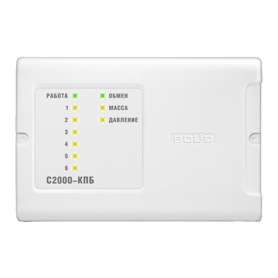
bolid S2000-KPB Manual de instruções - Página 6
Procurar online ou descarregar pdf Manual de instruções para Unidade de controlo bolid S2000-KPB. bolid S2000-KPB 17 páginas. Executive module
Também para bolid S2000-KPB: Manual de instruções (14 páginas)

When release circuits or explosion protected devices are being connected to the S2000-KPB then the
load connection modules can be located in the vicinity of the connected devices. An example of
connection diagram is shown in Figure 3.
The monitored states of a monitored circuit are defined by the circuit failure detection type
specified in the configuration parameters in accordance with Table 3.
Circuit Failure
Detection Type
1
2
3
4
When a monitored circuit is switched off its conditions are defined by the voltage on the positive
output terminal relative to the «0 V» terminal:
–
«Open Circuit Failure»: less than minus 1.125 V;
–
«Short Circuit Failure»: more than minus 0.15 V;
–
«Norm»: between minus 0.15 V and minus 1.125 V;
When a monitored circuit is switched on its conditions are defined by the current carrying through
the circuit:
–
«Short Circuit Failure»: More than 2.5A;
–
«Norm»: Less than 2.5 A but more than open-circuit current;
–
«Open Circuit Failure»: The value of the open-circuit current is defined depending on the
selected type of open-circuit failure monitoring in the unit configuration. The available variants
are shown in the table below.
Type of
Monitoring
0
1
2
3
4
o For the Disabled monitoring type the S2000-KPB doesn't monitor the circuit for open failures
when the output circuit is activated.
o For the Normal monitoring type the used minimum value of the output current is 5 mA.
o For the Programmable Open-Circuit Threshold monitoring type the minimum output current is
equal to an Open-Circuit Failure Current parameter from the unit's configuration. The value of the
parameter for each output can be set either while configuring the unit (see Section 3.3, Programming
the Unit) or standalone without connecting to a personal computer. For doing so switch on the relevant
outputs and ensure that all the connected executive devices operate properly. Then open the unit's
cover and perform a combination of presses on the tamper switch: short, long, long, long (dot dash
dash dash). A long press means holding the tamper switch pressed for 0.5 to 1.5 second while a short
press means holding the tamper switch pressed for shorter than 0.5 s. If pressing the combination has
succeeded than for each active output the unit generates a value of the Open-Circuit Failure Current
parameter less by eighth than the current value of output current. Also the Type of Open-Circuit
Failure Monitoring is changed for Programmable Open-Circuit Threshold while the indicators of the
relevant outputs pulse within 4 second in the mode "On for 0.75 s and off for 0.25 s".
6
The circuit is monitored both for open and short failures
The Types of Open-Circuit Failure Monitoring for a Switched-On Output
Table 3. The Types of Monitored Circuits
Monitored Conditions
No circuit condition is monitored
The circuit is monitored for open failures
The circuit is monitored for short failures
Table 4. The Types of Monitoring for a Switched-On Output
Disabled
Normal
Programmable Open-Circuit Threshold
Periodic Load Shutdown
Current Drop Monitoring
