bolid S2000-KPB Manual de instruções - Página 8
Procurar online ou descarregar pdf Manual de instruções para Unidade de controlo bolid S2000-KPB. bolid S2000-KPB 14 páginas. Executive module
Também para bolid S2000-KPB: Manual de instruções (17 páginas)
2.3 Device Failed Mode
The module switches to the Device Failed mode when it has found a fatal error on calculating the
checksum of the program memory of the built-in microprocessor.
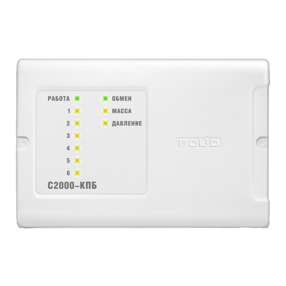
In the Device Failed mode READY and COM LEDs flash alternately while other indicators are lit
steady.
If the module enters the Device Failed mode on switching on, update its firmware by means of
ORION_PROG (download the last version from the Download section at http://bolid.ru) or return it
to the manufacturer.
3.1 Safety Precautions
3.1.1 The module has no circuits under hazardous voltage.
3.1.2 Do shut off the module's power before mounting, installing, or maintaining this one.
3.1.3 Mounting and maintaining must be performed only by qualified staff.
3.2 Preparations for Use
3.2.1 Before connecting the module to the RS-485 interface, the module must be assigned to a
unique network address. This address must not be the same as the address of another device connected
to the same interface RS-485.
3.2.2 If necessary, change other configuration parameters of the module to fit the module's
functions.
3.2.3 Attach the module at any convenient place (it can be installed on walls, behind suspended
ceilings and on other structures of the protected premises near executive devices at places protected
against atmospheric fallouts, mechanical damage, and unauthorized access).
3.2.4 Mount and wire the module as shown in Figure 3.
If a single power supply is in use (the configuration parameter Both Power Inputs Monitoring is set
off), this one can be connected to any power input of the module.
If the module and the network controller are connected to different power supplies, their 0 V
circuits should be coupled.
Unless the module is the end (the first or the last) device in the interface bus, remove the jumper
which is near the contacts "RS-485A" and "RS-485B".
8
3
OPERATIONAL DIRECTIVES