Akytec ITP15 Manual do utilizador - Página 9
Procurar online ou descarregar pdf Manual do utilizador para Instrumentos de medição Akytec ITP15. Akytec ITP15 10 páginas. Led bargraph indicator

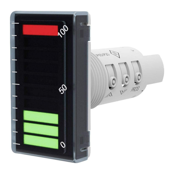
Each segment corresponds to 10% of the measurement range.
In case of a fault in the 4-20 mA and 2-10 V input circuit (short circuit or sensor break), the
three right and left extreme segments flash in red (Fig. 7.2) and the output is set to the state
defined in the parameter 3. "Output safe state" (Table 6.2).
For signals 0-20 mA and 0-10 V, short circuit and sensor break are indicated as 0%. The
output will not be set to the safe condition.
If the indication does not correspond to the real process value or when indicating an error,
check the set signal type matches the real signal (Table 6.2, parameter 1).
8. Maintenance
The device is maintenance free.
If necessary, the device should be cleaned with a damp cloth only. No abrasives or solvent-
containing cleaners may be used.
9. Transportation and storage
Pack the device in such a way as to protect it reliably against impact for storage and
transportation. The original packaging provides optimum protection.
If the device is not taken immediately after delivery into operation, it must be carefully stored
at a protected location. The device should not be stored in an atmosphere with chemically
active substances.
Permitted storage temperature: -25...+55 °C
The device may have been damaged during transportation.
►
NOTICE
Check the device for transport damage and completeness!
Report the transport damage immediately to the shipper and akYtec GmbH!
akYtec GmbH · Vahrenwalder Str. 269 A · 30179 Hannover · Germany Tel.: +49 (0) 511 16 59 672-0 ·
Fig. 7.1 Operation display
Fig. 7.2 Fault indication
www.akytec.de
8
