Baumer G0355 Instruções de montagem e manual do utilizador - Página 2
Procurar online ou descarregar pdf Instruções de montagem e manual do utilizador para Conversor de multimédia Baumer G0355. Baumer G0355 2 páginas. Incremental encoder, assignment c2, c3, c4, c5
Assembly Instructions
GB
GI355, GI356
G0355, G0356
GE355
Assignment C2, C3, C4, C5
Incremental Encoder
9
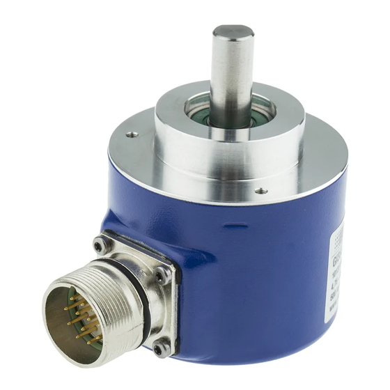
Connection – M23-Connector
Whilst not connected, the plug is always to be sealed by
the plastic cover provided by the manufacturer upon de-
livery.
Appropriate mating connectors available as spare part or
with different cable length, please refer to accessories. In
case of customer-specific length use only screened cable
and connectors corresponding to EMC standards.
- Turn mating connector carefully until the codemark is
interlocking the corresponding space provided by the
plug.
- Insert bushing completely.
- Tighten the nut as far as possible.
An optimized connection between encoder case
Connection:
C2, C3
and the braided shield of the connection cable is
only achieved by the braided shield being placed
generously onto the connector and the nut being
secured firmly.
8
9
1
12
10
7
2
3
6
Terminal assignment
11
5
4
Plug
Wire color
Assignment
Pin 1
pink
Track B inv.
Pin 2
blue
UB Sense
With clockwise
Pin 3
red
Track N (zero pulse)
rotation (cw)
Pin 4
black
Track N inv. (zero pulse inv.)
Pin 5
brown
Track A
Pin 6
green
Track A inv.
C4, C5
Pin 7
–
–
Pin 8
gray
Track B
Pin 9
–
–
1
9
8
Pin 10
white/green
GND
10
12
2
7
Pin 11
white
GND Sense
6
3
Pin 12
brown/green
UB
11
5
4
UB and UB Sense, GND and GND Sense are internally
connected.
With counter-
clockwise rotation
(ccw)
13
Danger
Warnings of possible danger.
General instructions
Information on appropriate product handling.
General remarks
Additional information
The installation instruction is supplementary to further
existing documentation (e.g. catalog, data sheet, manual).
It is imperative to read the manual carefully prior to star-
ting the device.
Appropriate use
9-16
- The encoder is a precision measuring device. It is expli-
citly designed for registration of angular positions and
revolutions as well as evaluation and supply of measu-
ring values as electric output signals for the subsequent-
ly connected device. The encoder must not be used for
any other purpose.
Start up
- Installation and assembly of the encoder only by electri-
cally skilled and qualified personnel.
- Consider also the operation manual of the machine
manufacturer.
Safety instructions
- All electrical connections are to be revised prior to star-
ting the system.
- Incorrect assembly and electrical connections or any
other inappropriate work at encoder and system may
lead to malfunction or failure of the encoder.
- Any risk of personal injury, damage of the system or
company equipment due to failure or malfunction of the
encoder has to be eliminated by corresponding safety
measures.
- Do not operate encoder beyond the limit values stated
in the data sheet.
Any disregard may lead to malfunctions, material damage
and personal injury.
10
Dimensions
GI355, G0355, GE355 clamping flange
14
Disposal
Encoder components are to be disposed of according to
the regulations prevailing in the respective country.
Transport and storing
- In original packing only.
- Do not drop or expose encoder to major shocks.
Assembly
- Avoid punches or shocks on case and shaft.
- Avoid case distortion.
- Do not use any rigid links between encoder shaft and
drive shaft.
- Do not open or modify encoder in any mechanical way.
Shaft, bearing, glass disc or electronic componen-
ts might be damaged and a secure operation is no
longer guaranteed.
Mechanical assembly
- Mount encoder using three screws using the three
Fixing bore
fixing bores of the flange. Consider the depth and dia-
meter of the thread.
Eccentric
- Alternative mounting in any angular position is possible
fixing
by means of three eccentric fixings, please refer to
accessories.
- Use appropriate coupling to link drive shaft and enco-
der shaft. For appropriate links please refer to acces-
sories.
The ends of the shafts must not touch each other.
Any displacements due to temperature or me-
69
chanical tolerances have to be equalized by the
coupling. Mind the maximum permitted axial or
radial shaft load. Tighten fixing screws firmly.
11
Dimensions
GI356, G0356 synchro flange
15
Electrical installation
- Do not modify encoder in any electrical way and carry
out any wiring work under power supply.
- Any electrical connection and plugging-on whilst under
power supply is not permitted.
- A separate encoder supply has to be provided with con-
sumers with high interference emission.
- Encoder case and supply cable have to be completely
screened.
- Installation of the whole system has to be according
to EMC standards. Installation environment as well as
wiring have an impact on the encoder's EMC. Encoder
and supplying lines are to be in separated locations or
remote from lines with high interference emission (fre-
quency transformers, protections, etc.).
- Ground (PE) encoder by using screened cables. The
braided shield has to be connected to cable gland or
plug. Grounding (PE) on both sides is recommended.
Ground the case by the mechanical assembly, if latter
is electrically isolated a second connection has to be
provided. Ground cable screen by the subsequently
connected devices. In case of ground loop problems at
least grounding on one side is imperative.
Any disregard may lead to malfunctions, material damage
and personal injury.
Electrical connection
Any outputs not used must not be connected.
Unused cable cores have to be isolated.
Output driver
If the operating voltage is off, do not pulse the outputs
(track) by voltage (danger of destruction).
Provide a terminator at the end of the output connecting
lines, otherwise the output driver might be subject to over-
load by line reflections.
Connection – Cable
- Max. bending radius 90 mm.
12
16