Baumer GXAMW Manual - Página 8
Procurar online ou descarregar pdf Manual para Conversor de multimédia Baumer GXAMW. Baumer GXAMW 41 páginas. Absolute encoder with powerlink interface
Também para Baumer GXAMW: Manual (19 páginas), Manual (26 páginas), Manual (24 páginas), Manual (19 páginas)
4. Commissioning
4.1. Mechanical mounting
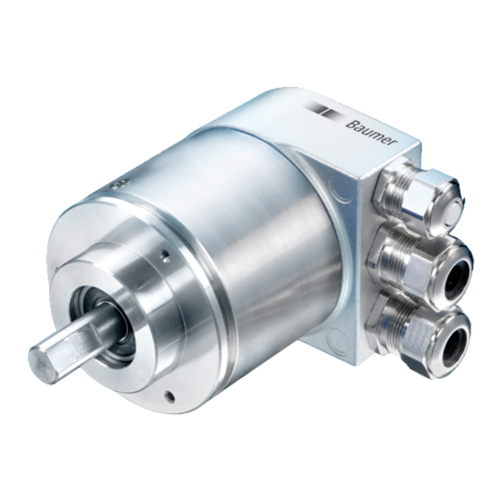
Shaft encoders
Mount the encoder by help of the mounting holes and three screws (square flange: 4 screws) provided at
the encoder flange. Observe thread diameter and depth.
There is an alternative mounting option in any angular position by eccentric fixings, see under
accessories.
Connect drive shaft and encoder shaft by using an appropriate coupling. The shaft ends must not touch
each other. The coupling must compensate temperature and mechanical tolerances. Observe the
maximum permitted axial or radial shaft load. For appropriate couplings please refer to accessories.
Tighten the mounting screws firmly.
End shaft/hollow shaft encoders
Mounting by clamping ring
Prior to mounting the encoder open the clamping ring completely. Push encoder onto the drive shaft and
tighten the clamping ring firmly.
Adjusting element with rubber buffer
Push the encoder onto the drive shaft and insert the cylindrical pin into the adjusting element (provided by
customer) and the rubber buffer.
Adjusting angle
Push the encoder onto the drive shaft. Insert adjusting angle into the encoder's rubber buffer and fasten
the adjusting angle at the contact surface.
Stud screw
Push the encoder onto the drive shaft and insert the stud screw provided by customer into the encoder's
rubber buffer.
Spring coupling
Fasten the spring coupling at the mounting holes of the encoder housing using screws. Push the encoder
onto the drive shaft and mount the spring coupling to the contact surface.
4.2. Electrical connection
Ever store and transport the bus cover in the ESD bag only.
For electrical connection remove the bus cover as follows:
Release the fastening screws of the bus cover
Carefully loosen the bus cover and lift off in an axial direction
4.2.1.
Cabling
EN 50170 specifies two types of PROFIBUS cable, type A and B. Type B is obsolete and should not be used
in new applications. With type A all transmission rates up to 12Mbit/s are possible. Common baud rate in
clock synchronous operation according to PROFIBUS-DPV2 is 12Mbit/s.
Properties
Impedance in Ohm
Operating capacity (pF/m)
Loop impedance (Ohm/km)
Core diameter (mm)
Core cross section (mm)
Transmission speed depending on line distance
Baudrate in
9,6
kBaud
Line distance
1200
in m
Manual_ProfibusDPV2_BIDE_EN.docx
22.11.12
19,2
93,75
187,5
1200
1200
1000
Data
135 to 165 at 3 to 20 MHz
less than 30
less than 110
greater than 0.64
greater than 0.34
500
1500
400
200
8/41
3000
6000
12000
100
100
100
Baumer IVO GmbH & Co. KG
Villingen-Schwenningen, Germany