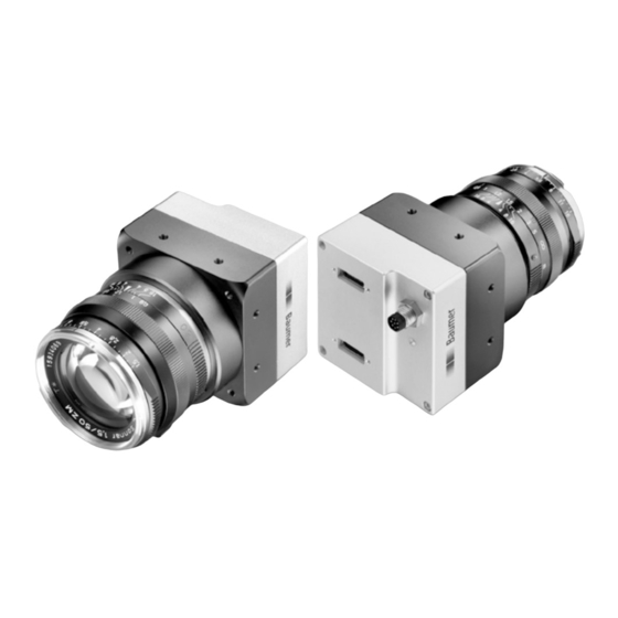
Baumer LXC-120M Manual de início rápido - Página 2
Procurar online ou descarregar pdf Manual de início rápido para Câmara digital Baumer LXC-120M. Baumer LXC-120M 2 páginas.

General Description
1
No.
Description
No.
Description
C-Mount
C-mount only
1
4
Signaling-LED
M58-Mount
lens mount (M58), adapter for
other lens mounts available
Camera Link
®
socket
Camera Link
2
5
(Base)
(Medium / Full / EightyBit)
3
Power Supply / Digital-IO
Camera Link
®
sockets
Notice
The camera has two Camera Link
®
CL BASE
Baumer
Type: XXXXXx
ween Camera Link
®
socket, please look at the label. You can not
(xxxxxxx)
use the CL Medium / Full / EightyBit socket alone!
CL FULL
Notice
To use Power over Camera Link
®
(PoCL, 12V DC ± 20%), both Camera Link
sockets must be used.
Camera Link
®
(Base)
(Medium / Full / EightyBit)
Pin
Signal
Pin
Signal
Pin
1
GND
14
GND
1
GND
2
X0-
15
X0+
2
Y0-
3
X1-
16
X1+
3
Y1-
4
X2-
17
X2+
4
Y2-
5
18
5
XCLK-
XCLK+
YCLK-
6
X3-
19
X3+
6
Y3-
7
SERTC+
20
SERTC-
7
100 Ω term.
8
SERTFG-
21
SERTFG+
8
Z0-
9
CC1-
22
CC1+
9
Z1-
10
23
10
CC2+
CC2-
Z2-
11
CC3-
24
CC3+
11
ZCLK-
12
CC4+
25
CC4-
12
Z3-
13
GND
26
GND
13
GND
LED Signaling
2
3
4
5
LED
®
socket
Power Supply and Process Interface
Caution
sockets. To differentiate bet-
A power supply with electrical isolation is required for proper operation of
the camera. Otherwise the device may be damaged!
®
Camera Link
®
Signal
Pin
Signal
14
GND
15
Y0+
16
Y1+
17
Y2+
18
YCLK+
19
Y3+
20
100 Ω term.
21
Z0+
22
Z1+
23
Z2+
24
ZCLK+
25
Z3+
26
GND
LED
Signal
Meaning
green on
Power on, link good
green blinking
Power on, no link
red on
Error / Overtemperature
Boot process or Warning
red blinking
(update in progress, don't switch off)
yellow
Readout active
Power Supply / Digital-IO
M8 / 8 pins wire colors of the connecting cable
3
4
2
5
8
6
1
7
1
white
not in use
2
brown
Power VCC+
3
green
IN 1 (line 0)
4
yellow
IO GND
5
grey
IO Power VCC
6
pink
OUT 1 (line 1)
7
blue
Power GND
8
red
not in use
Power Supply
Power VCC
12 VDC ... 24 VDC ± 20%
Heat Transmission
Caution
Provide adequate dissipation of heat, to ensure that the temperature
does not exceed +50 °C (+122 °F).
The surface of the camera may be hot during operation and immediately
after use. Be careful when handling the camera and avoid contact over a
longer period.
As there are numerous possibilities for installation, Baumer do not speci-
fiy a specific method for proper heat dissipation, but suggest the following
principles:
▪ operate the cameras only in mounted condition
▪ mounting in combination with forced convection may provide proper
heat dissipation
T
Measure Point
Maximal Temperature
T
+50 °C (122 °F)
General notes for electrical Installation
Caution
Follow the instructions in the chapter „Hardware installation Procedure"
of the User´s Guide.
Failure to follow the instructions may result in problems during operation
and defects in the camera!
ESD precautions:
▪ Wear ESD appropriate clothing and shoes.
▪ Perform the installation in an ESD-compliant working environment (conductive
floors, grounding strap, ...).
▪ Never handle the Camera Link connectors without ESD discharge!
▪ Control the humidity in your environment. Low humidity can cause ESD problems.
Notes on cable routing and avoiding ground loops:
▪ To avoid ground loops, the power supply cable and the Camera Link cables should
be routed in parallel if possible.
▪ All electrical connections must be brought together at a ground point.
▪ The ground point should be as close as possible to the frame grabber of the PC.
The PC must be included in the grounding.
▪ Avoid laying power supply cables of devices with high current peaks, e.g. motors
or inverters, parallel to the camera cables.
T
