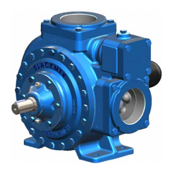
Dover Blackmer LGL3021A Instruções de instalação, operação e manutenção - Página 6
Procurar online ou descarregar pdf Instruções de instalação, operação e manutenção para Bomba de água Dover Blackmer LGL3021A. Dover Blackmer LGL3021A 12 páginas. Liquefied gas pumps

PRE-START UP CHECK LIST
1.
Inspect complete piping system and supports to ensure
that no piping loads are being placed on the pump.
2.
Verify proper coupling or V-belt alignment.
3.
Install pressure gauges in the 1/4" NPT intake and
discharge ports located on the pump casing to check
pump performance after start-up.
4.
Ensure all valves and fittings in piping system are in the
start-up or operating positions.
5.
Jog the pump motor to verify proper pump rotation.
START UP PROCEDURES
NOTICE:
Consult the "Troubleshooting" sections of this manual if
difficulties during start up are experienced.
1.
SLOWLY build pressure in the pump.
2.
Start the motor.
3.
Check pressure gauges to ensure the system is
operating within expected parameters. Record the gauge
readings in the "Initial Start Up Information" section of
this manual for future reference.
4.
Inspect piping, fittings, and associated system equipment
for leaks, noise, vibration and overheating.
Failure to set the vehicle emergency
brake and chock wheels before
performing service can cause severe
personal injury or property damage.
Hazardous pressure
can cause personal
injury or property
damage
NOTICE:
Consult the "General Installation and Operation" section
of this manual for system information.
TRUCK MOUNTING
The pump will operate satisfactorily in any position. When
locating the pump on a tank, safety should be the first
consideration. The pump can be bolted to the truck frame or
on a saddle hung below the frame, and MUST be adequately
supported.
MOTOR DRIVEN PUMPS
5.
6.
7.
8.
TRUCK MOUNTED PUMPS
PUMP DRIVE
The pump may be driven by a power take-off through
universal joints. When using universal joints, a splined slip
joint, properly lubricated, must be used on the connecting jack
shaft to prevent end thrust on the pump shaft. It is very
important to install a proper drive line to avoid excessive
wear, vibration and noise (see Fig. 7 and Table 2).
General guidelines to follow for proper pump drive:
1.
2.
3.
4.
5.
6.
Failure to follow any of these guidelines may result in a gallop
or uneven turning of the pump rotor, which will in turn cause a
surging vibration to the liquid stream and piping system.
Contact the supplier of the drive line components for specific
design assistance.
501-L00
Page 6/12
Check the flow rate to ensure the pump is operating
within the expected parameters. Record flow rate in the
"Initial Start Up" section of this manual.
Close the discharge valve and check the differential
pressure across the pump. Pressure must not exceed the
pressure setting of the external bypass valve.
With the discharge valve still closed, momentarily close
the manual shut-off valve in the bypass return line to
check the pump internal relief valve. The differential
pressure will be approximately 150 and 170 PSI (10.3
and 11.7 bar).
The external bypass valve must always be set at least 25
PSI (1.7 bar) lower than the internal pump relief valve.
NOTE: The normal operating pressure must be at least 5
- 15 PSI (0.3 -1.0 bar) less than the external bypass
valve setting. Pump speeds which result in higher
pressures (nearing the valve setting) forces the liquid to
recirculate, creating excessive wear on the pump and
equipment.
Pumps operating against a closed valve
can cause system failure, personal
injury and property damage
Hazardous pressure
can cause personal
injury or property
damage
Do not use square slip joints.
Use the least number of jack shafts as is practical.
Use an even number of universal joints.
The pump shaft and power take-off shaft must be parallel
in all respects. Use an angular level measuring device to
ensure the PTO and pump shaft are parallel to each
other. If necessary, the pump can be shimmed to correct
any misalignment. The PTO shaft coming off at the
transmission does not need to be perfectly horizontal as
long as the pump is shimmed to have its shaft parallel in
all respects to the PTO shaft.
The yokes of the universals at both ends of the jack shaft
must be parallel and in phase.
The maximum recommended angle between the jack
shaft and the pump shaft is 15 degrees. See Table 2.
