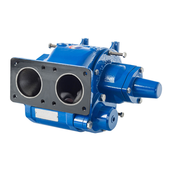
Dover PSG Mouvex CC10-24 Instalação, operação e manutenção - Página 6
Procurar online ou descarregar pdf Instalação, operação e manutenção para Bomba de água Dover PSG Mouvex CC10-24. Dover PSG Mouvex CC10-24 18 páginas.

3.1 Choice of pump
To obtain the service expected from a MOUVEX pump, regar
ding both performance and longevity, it is vital that the type
of pump, its speed and the materials used for its construction
are determined as a function of the pump output, its installa
tion and operating conditions.
The association of the pump CC1024 with a gas separator (EC
type from SATAM or equivalent) is prohibited because it poten
tially generates pulses.In this case, it is necessary to favor the
use of a CC840, CC850 or CC865 which will give complete
satisfaction.
You can contact our Technical Services at any time to ask for
the information you require.
3.2 Direction of rotation
The pump rotates in one direction only. This is indicated by an
arrow on the pump housing. However, the pump has both of
shaftends led out and must be driven through one the other
depending on the direction of rotation of the power takeoff.
Because the pump rotates in one direction only, the positions
of the suction and discharge ports are not be reversed (see
arrows on housing). The safety bypass has not to be reversed.
3.3 Pump protection
It is essential to protect the pump against possible foreign
matter by connecting a filter to the suction pipe (see
Instructions 1011G00 F
3.4 Pipe diameter
In order to achieve the best usage conditions, it is important
to take the following recommendations into account when it
comes to pipe dimensions :
• The pipe diameter should be chosen as a function of pipe
length and the flow rate and viscosity of the pumped liquid,
so that any head loss remains within the permissible limits
for the motor/pump unit. Therefore it is difficult to give general
and precise directions. However, it is never a disadvantage to
overdimension pipe diameters, especially for the section on
the inlet side.
• In the case of thin liquids and the piping on the discharge
side, one can generally allow a diameter equal to that of the
ports on the pump and a larger diameter for the piping on
the inlet side, if the value for the inlet power of the pump is
negative or especially high.
Our Technical Services are always available to provide you
with precise data if you give them accurate information or,
better still, the installation plans.
NT 1010P00 09 20 CC1024 A e
3. INSTALLATION
PF).
ILTERS
3.5 Piping assembly
In order to achieve the best usage conditions, it is important
to take the following recommendations into account when it
comes to fitting pipes :
• The location of the pump in the transfer or recycling circuit
should always be determined so as to reduce the height and
length of the piping as much as possible.
• Wherever possible, siphons and reverse slopes should be
avoided in the inlet piping.
• Particular care needs to be taken with the sealing on the
inlet side to prevent air entering.
• Pipe elbows must always have a large radius (more than 3
times the diameter of the pipes) and must not be mounted
too close to the pump flanges (min. recommended distance :
10 times the diameter of the pipes), on both the inlet and
discharge sides.
• The pipes are supported and aligned with the pump in such
a way as to avoid putting stress on the pump flanges. Non
compliance with this instruction can lead to deformation of
pump parts, misalignment of bearings and accelerated
material wear, even causing parts to break.
• For ease of adjustment and checking, it is recommended that
pressure tapping ports for pressure gauges/vacuum gauges
be provided as close as possible to the pump's inlet ports
(preferably, at a distance of less than 5 times the diameter
of the piping).
• If the suction head is especially high or if you want to prevent
the pipes emptying at shutdown, you can install a foot valve.
It should have a large diameter so as not to generate addi
tional head loss.
• We recommend placing valves as close as possible to the
pump ports to avoid having to drain the entire system each
time maintenance is carried out. These valves should have
the same diameter as the pipes and preferably by full bore
models.
• All these steps should be taken to prevent foreign bodies
entering the pump (the use of a filter in the pump inlet pipe
is strongly recommended).
• Before installing new pipes or tanks, be sure to clean them
very carefully to remove any solder, rust, etc. which could be
carried along with the water and cause excessive pump wear.
• The pipes should be designed to allow for thermal expan
sion/contraction (the use of flexible hoses or expansion loops
is recommended).
• If the liquid may freeze or solidify, prepare for draining the
piping by installing drain taps at the low points and air vents
at the high points.
6/18
