Advanced Air 0160 Series Manual de instalação, operação e manutenção - Página 11
Procurar online ou descarregar pdf Manual de instalação, operação e manutenção para Amortecedores de fogo e fumo Advanced Air 0160 Series. Advanced Air 0160 Series 13 páginas. Air control fire damper
Também para Advanced Air 0160 Series: Manual de início rápido (14 páginas)

FIRE – 0160 HEVAC FOR RIGID SUPPORTING CONSTRUCTION (FLOOR)
Turnback tabs
HEVAC frame
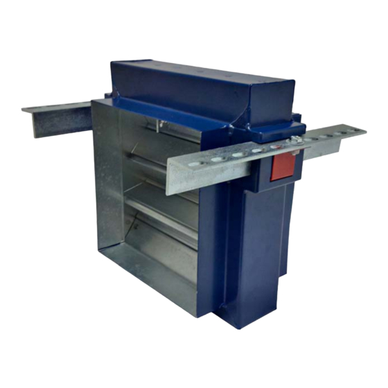
0160 Series fire damper
0160 W/HEVAC
PRODUCT
BRE 287811D
CLASSIFICATION REPORT NO.
TESTED INSTALLATION METHOD SHOWN. DIFFERING INSTALLATION METHODS TO THIS MUST BE APPROVED BY THE BUILDING CONTROL AUTHORITY (BCA) BEFORE PROCEEDING.
Preparation
1
Ensure that the damper is kept
in a clean dry environment and
that there is no damage to the
damper.
2
Remove all the packaging and
transit ties before installation.
3
Work out the opening size to be
Access door
cut using the adjacent table.
for inspection /
damper reset
Installation sequence
4
In the opening, mark the positions for the turnback tabs on the HEVAC frame, making sure that the
HEVAC casing will sit flush with the floor surface.
5
Create 20mm deep pockets for the HEVAC tabs to be located in.
6
Offer up the damper into the opening and support from below or clamp angles spanning the opening.
7
Bend the HEVAC tabs so that they lock into the pockets.
8
Fire batt of a minimum 25mm thickness and density of 140kg/m² shall be installed under the damper
frame to serve as shuttering to facilitate installation of the penetration seal all around the damper.
Rigid construction
9
A 4:1 mortar mix can then be gradually applied between the floor and the damper, ensuring the mortar
is only filled up to the HEVAC frame and not the damper spigots. This ensures the damper can move
4:1 mortar mix
within the HEVAC frame.
10
The fire batt shall remain in situ after the mortar has been applied.
11
The galvanised mild steel ductwork connecting to the damper spigots must overlap by up to 40mm,
leaving minimum 10mm clearance for any duct expansion in a fire situation.
12
The galvanised mild steel ductwork connections must be sealed with an approved galvanised mild
steel ductwork sealer and fixed with low resistance fixings such as aluminium rivets that will melt at
high temperature allowing the duct to break away without affecting the integrity of the installation.
13
The connecting galvanised mild steel ductwork must be independently supported within one metre of
the connections and have been installed in accordance with DW144.
14
An access door should be fitted on the access side of the damper to enable the resetting of the
damper blades.
Fire batt
15
When the damper installation has been completed, checks should be made to ensure the damper is
secure and there is no movement, operation of the damper should be checked.
16
Complete DW145 Fire Damper Certificate.
RIGID CONSTRUCTION (FLOOR)
APPLICATION
E120 (HO I O
CLASSIFICATION
Nom. duct width
Opening width min.
Opening width max.
100-1,000mm
Nom. duct +160mm
Nom. duct +185mm
Nom. duct height
Opening height min.
Opening height max.
100mm
Nom. duct +160mm
Nom. duct +185mm
101-300mm
Nom. duct +185mm
Nom. duct +210mm
301-525mm
Nom. duct +210mm
Nom. duct +235mm
526-700mm
Nom. duct +235mm
Nom. duct +260mm
701-925mm
Nom. duct +260mm
Nom. duct +285mm
926-1,000mm
Nom. duct +285mm
Nom. duct +310mm
11
