Amprobe CT-400 Manual de início rápido - Página 8
Procurar online ou descarregar pdf Manual de início rápido para Sensores de segurança Amprobe CT-400. Amprobe CT-400 10 páginas. At-6000 series. advanced wire tracer

AT-6000 Advanced Wire Tracer Series - Quick Guide
Special Application: Metal Conduit
1
Set-up:
Test Leads
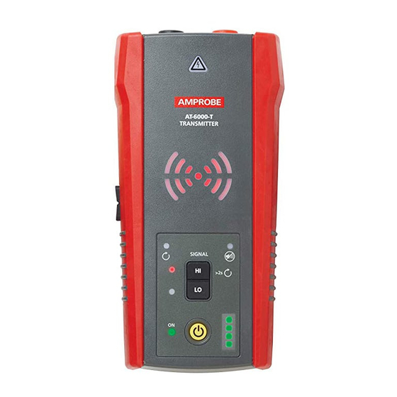
TRANSMITTER
Proper connection
with separate
ground
1. Connect the green and red test leads to the
Transmitter.
2. Plug the socket adapter onto the receptacle
and connect the red lead to the Energized
hot wire. The signal will only betransmitted
between the load-side to which the Transmitter
is connected and the source of power.
3. Connect the green wire to a separate ground.
2
Set-up:
Transmitter
Blinking
Transmitter indicator
showing signal in
HIGH mode
1. Turn on the Transmitter.
2. Verify that the test leads are properly connected;
the red LED voltage status light should be on
for circuits with voltage above 30 V AC/DC, and
it should be off for De-energized circuits below
30 V AC/DC.
3. Select HIGH signal mode by pressing HI, LED
display will quickly begin to blink.
6
AT-6000-T
HI
LO
AT-6000-T
TRANSMITTER
HI
LO
1
Set-up:
Receiver
Precision
tracing mode
NCV
1. Turn on the Receiver. Press the MODE
button to select a wire tracing mode (either
Quick Scan or Precision Tracing). Tracing).
Receiver:
Tracing Wires in
Metal Conduit
1. Open junction boxes and use the Receiver Tip
Sensor to detect which wire in the junction
box is carrying the signal.
2. Move from junction box to junction box to
follow the path of the wire.
Important Notes:
Applying a signal directly to the conduit will send the
signal through all the conduit branches, making tracing a
particular conduit path impossible.
The Receiver is unable to pick up the signal from a
wire through a metal conduit. The metal conduit will
completely shield the tracing signal. The Receiver will be
able to detect wires in a non-metallic conduit. For these
applications follow general tracing guidelines.
88
