DPS NetGuardian 864 Manual de início rápido - Página 8
Procurar online ou descarregar pdf Manual de início rápido para Controlador DPS NetGuardian 864. DPS NetGuardian 864 17 páginas. Hinged back panel

5
4.2
Pinout of NetGuardian 864A
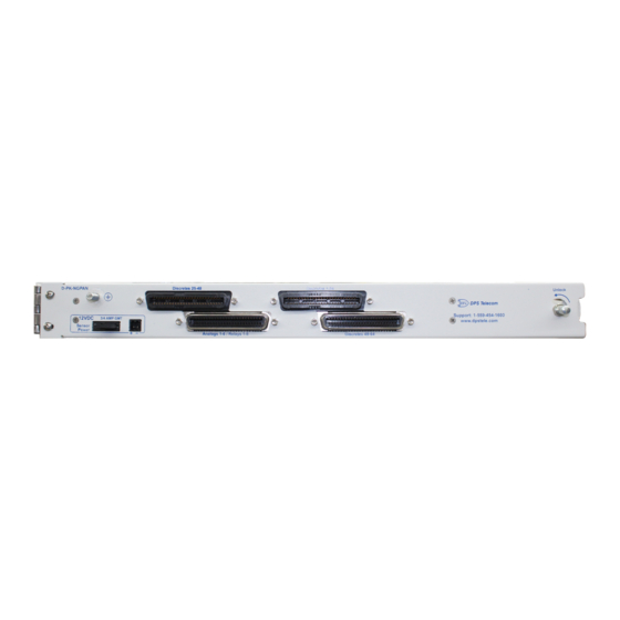
The NetGuardian 864's discrete alarm inputs, control relay outputs, and first six analog alarm inputs are connected
through the two 50-pin connectors labeled "Discretes 1–24" and "Analogs 1–6/Discretes 25–32/Relays 1–8" on the
back panel. Analog alarm inputs 7 and 8 are connected through the four-pin connector labeled "Analogs 7–8."
4.2.1 Alarm and Control Relay Connector Pinout Table
Discretes 1–48
ALM
PIN
1
26
2
1
3
27
4
2
5
28
6
3
7
29
8
4
9
30
10
5
11
31
12
6
13
32
14
7
15
33
16
8
17
34
18
9
19
35
20
10
21
36
22
11
23
37
24
12
25
38
GND/RTN*
Table 7.B. Alarm and relay connection pinouts for NetGuardian 864
RTN* is the alarm return pin. Alarms on standard units are dry closure or ground closure. Most units will
have RTN internally tied to GND. However, special hardware assemblies may have RTN isolated from
GND.
Alarm and control relay connectors
Discretes 49-64, Relays 1-8, Analogs 1-6
ALM
PIN
ALM
26
13
49
27
39
50
28
14
51
29
40
52
30
15
53
31
41
54
32
16
55
33
42
56
34
17
57
35
43
58
36
18
59
37
44
60
38
19
61
39
45
62
40
20
63
41
46
64
42
21
43
47
44
22
45
48
46
23
47
49
48
24
GND
25
50
PIN
Relays 1-8
26
RLY 1
1
RLY 2
10
27
RLY 3
11
2
RLY 4
12
28
RLY 5
13
3
RLY 6
14
29
RLY 7
15
4
RLY 8
16
30
FUSE
17
5
ADC
31
ADC 1
19
6
ADC 2
20
32
ADC 3
21
7
ADC 4**
22
33
ADC 5**
23
8
ADC 6**
24
GND
25
GND/RTN*
50
Analogs 7-8
ADC
+
7
B
9
34
8**
B
35
36
37
38
39
40
41
42
+
-
44
45
46
47
48
49
-
A
A
